
m0n0wall Version 1.2 and 1.3b
Copyright © 2008 m0n0wall Documentation Project
All rights reserved.
Redistribution and use in any form, with or without modification, are permitted provided that the following conditions are met:
Redistributions must retain the above copyright notice, this list of conditions and the following disclaimer.
Neither the name of the m0n0wall Documentation Project nor the names of its contributors may be used to endorse or promote products derived from this documentation without specific prior written permission.
THIS DOCUMENTATION IS PROVIDED BY THE COPYRIGHT HOLDERS AND CONTRIBUTORS "AS IS" AND ANY EXPRESS OR IMPLIED WARRANTIES, INCLUDING, BUT NOT LIMITED TO, THE IMPLIED WARRANTIES OF MERCHANTABILITY AND FITNESS FOR A PARTICULAR PURPOSE ARE DISCLAIMED. IN NO EVENT SHALL THE COPYRIGHT OWNER OR CONTRIBUTORS BE LIABLE FOR ANY DIRECT, INDIRECT, INCIDENTAL, SPECIAL, EXEMPLARY, OR CONSEQUENTIAL DAMAGES (INCLUDING, BUT NOT LIMITED TO, PROCUREMENT OF SUBSTITUTE GOODS OR SERVICES; LOSS OF USE, DATA, OR PROFITS; OR BUSINESS INTERRUPTION) HOWEVER CAUSED AND ON ANY THEORY OF LIABILITY, WHETHER IN CONTRACT, STRICT LIABILITY, OR TORT (INCLUDING NEGLIGENCE OR OTHERWISE) ARISING IN ANY WAY OUT OF THE USE OF THIS DOCUMENTATION OR THE ASSOCIATED SOFTWARE, EVEN IF ADVISED OF THE POSSIBILITY OF SUCH DAMAGE.
June 2008

Table of Contents
- 1. Introduction
- 2. Hardware Compatibility
- 3. Setup
- 4. Configuration
- 5. The Firewall Screens
- 6. Network Address Translation
- 7. Traffic Shaper
- 8. IPsec
- 9. PPTP
- 10. OpenVPN
- 11. Wireless
- 12. Captive Portal
- 13. Example Configurations
- 14. Example IPSec VPN Configurations
- 15. FAQ
- 15.1. How do I setup mobile user VPN with IPsec?
- 15.2. How can I prioritize ACK packets with m0n0wall?
- 15.3. Why isn't it possible to access NATed services by the public IP address from LAN?
- 15.4. I enabled my PPTP server, but am unable to pass traffic into my LAN
- 15.5. I just added a new interface to my m0n0wall box, and now it doesn't show up in the webGUI!
- 15.6. Does m0n0wall support MAC address filtering?
- 15.7. Does m0n0wall support SMP systems?
- 15.8. Why can't hosts on a NATed interface talk to hosts on a bridged interface?
- 15.9. What were the goals behind the m0n0wall project?
- 15.10. How do I setup multiple IP addresses on the WAN interface?
- 15.11. Can I filter/restrict/block certain websites with m0n0wall?
- 15.12. Why are some passwords stored in plaintext in config.xml?
- 15.13. Are there any performance benchmarks available?
- 15.14. What about hidden config.xml options?
- 15.15. Why can't I query SNMP over VPN?
- 15.16. Can I use m0n0wall's WAN PPTP feature to connect to a remote PPTP VPN?
- 15.17. Can I use multiple WAN connections for load balancing or failover on m0n0wall?
- 15.18. Can I access the webGUI from the WAN?
- 15.19. Can I access a shell prompt?
- 15.20. Can I put my configuration file into the m0n0wall CD?
- 15.21. How can I monitor/graph/report on bandwidth usage per LAN host?
- 15.22. Will there ever be translated versions of m0n0wall? Can I translate m0n0wall into my language?
- 15.23. Does m0n0wall support transparent proxying?
- 15.24. Should I use m0n0wall as an access point?
- 15.25. Why am I seeing traffic that I permitted getting dropped?
- 15.26. How can I route multiple subnets over a site to site IPsec VPN?
- 15.27. How can I block/permit a range of IP addresses in a firewall rule?
- 15.28. Why does my MSN Messenger transfer files very slowly when using traffic shaper?
- 15.29. Can I forward broadcasts over VPN for gaming or other purposes?
- 15.30. How can I use public IP's on the LAN side? Or how can I disable NAT?
- 15.31. Are PCMCIA cards supported?
- 15.32. Are there any tweaks for systems that will need to support large loads?
- 15.33. Can I add MRTG or some other historical graphing package to m0n0wall?
- 15.34. Can Captive Portal be used on a bridged interface?
- 15.35. Can I run Captive Portal on more than one interface?
- 15.36. Why do my SSH sessions time out after two hours?
- 15.37. Why isn't the reply address of the list set to the list?
- 15.38. Why am I seeing "IP Firewall Unloaded" log/console messages?
- 15.39. Why can't my IPsec VPN clients connect from behind NAT?
- 15.40. Why doesn't m0n0wall have a log out button?
- 15.41. Can I have more than 16 simultaneous PPTP users?
- 15.42. Can I sell m0n0wall (or use it in a commercial product)?
- 15.43. Where can I get a high-resolution version of the m0n0wall logo?
- 15.44. When will m0n0wall be available on a newer FreeBSD version?
- 15.45. Is there any extra Captive Portal RADIUS functionality available?
- 15.46. How can I increase the size of the state table?
- 16. Other Documentation
- 17. Troubleshooting
- 17.1. Interfaces are not detected
- 17.2. After replacing my current firewall with m0n0wall using the same public IP, m0n0wall cannot get an Internet connection.
- 17.3. No Link Light
- 17.4. Cannot Access webGUI
- 17.5. Cannot Access Internet from LAN after WAN Configuration
- 17.6. Troubleshooting Firewall Rules
- 17.7. Troubleshooting Bridging
- 17.8. Troubleshooting IPsec Site to Site VPN
- 17.9. Troubleshooting Solid Freezes
- 18. Bibliography
- Glossary
- A. Reference
- B. Third Party Software
- B.1. Introduction
- B.2. Installing SVG Viewer on Mozilla Firefox
- B.3. Collecting and Graphing m0n0wall Interface Statistics with ifgraph
- B.4. Updating more than one Dynamic DNS hostname with ddclient
- B.5. Using MultiTech's Free Windows RADIUS Server
- B.6. Configuring Apache for Multiple Servers on One Public IP
- B.7. Opening Ports for BitTorrent in m0n0wall
- B.8. Automated config.xml backup solutions
- B.9. Historical Interface Graphing Using MRTG on Windows
- C. License
- C.1. The FreeBSD Copyright
- C.2. The PHP License
- C.3. mini_httpd License
- C.4. ISC DHCP Server License
- C.5. ipfilter License
- C.6. MPD License
- C.7. ez-ipupdate License
- C.8. Circular log support for FreeBSD syslogd License
- C.9. dnsmasq License
- C.10. racoon License
- C.11. General Public License for the software known as MSNTP
- C.12. ucd-snmp License
- C.13. choparp License
- C.14. bpalogin License
- C.15. php-radius License
- C.16. wol License
- Index
List of Figures
- 4.1. The General Setup screen
- 4.2. The Firmware screen
- 4.3. The System Status screen
- 4.4. The Traffic Graph screen
- 8.1. Example: m0n0wall behind a router
- 13.1. Example Network Diagram
- 13.2. Filtered Bridge Diagram
- 14.1. Network diagram
- 14.2. Example of Sonicwall configuration
- 17.1. Trobleshooting Internet Access
- 11. Typical DMZ Network
List of Tables
- 4.1. General Setup parameters
- 4.2. Advanced System Options
- 4.3. SIP Proxy Parameters
- 4.4. Log Settings Parameters
- 4.5. The two entries for each VPN connection are as follows:
- 8.1. IPSec Feature List
- 11.1. Wireless 1.2 Parameters
- 11.2. Wireless 1.3 Parameters
- 12.1. Connection Parameters
- 12.2. Secure Authentication Parameters
- 12.3. User Parameters
- 12.4. Radius Server Parameters
- 12.5. Voucher Parameters
- 12.6. Voucher Roll Parameters
Table of Contents
m0n0wall is a complete embedded firewall software package that, when used together with an embedded PC, provides all the important features of commercial firewall boxes (including ease of use) at a fraction of the price (free software). m0n0wall is based on a bare-bones version of FreeBSD, along with a web server (thttpd), PHP and a few other utilities. The entire system configuration is stored in one single XML text file to keep things transparent.
m0n0wall is probably the first UNIX system that has its boot-time configuration done with PHP, rather than the usual shell scripts, and that has the entire system configuration stored in XML format.
m0n0wall is a firewall, and the purpose of a firewall is to provide security. The more functionality is added, the greater the chance that a vulnerability in that additional functionality will compromise the security of the firewall. It is the opinion of the m0n0wall founder and core contributors that anything outside the base services of a layer 3 and 4 firewall do not belong in m0n0wall. Some services that may be appropriate are very CPU-intensive and memory hungry, and m0n0wall is focused towards embedded devices with limited CPU and memory resources. The non-persistant filesystem due to our focus on Compact Flash installations is another limiting factor. Lastly, image size constraints eliminate other possibilities.
We feel these services should be run on another server, and are intentionally not part of m0n0wall:
Intrusion Detection/Prevention System
Proxy Server
Packet inspection at any layers other than 3 and 4
A general purpose web server
An FTP server
A network time server
A log file analyzer
For the same reason, m0n0wall does not allow logins: there is no login prompt at the console (it displays a menu instead), and no telnet or ssh daemon.
Manuel Kasper, m0n0wall's author, says:
Ever since I started playing with packet filters on embedded PCs, I wanted to have a nice web-based GUI to control all aspects of my firewall without having to type a single shell command. There are numerous efforts to create nice firewall packages with web interfaces on the Internet (most of them Linux based), but none met all my requirements (free, fast, simple, clean and with all the features I need). So, I eventually started writing my own web GUI. But soon I figured that I didn't want to create another incarnation of webmin ? I wanted to create a complete, new embedded firewall software package. It all evolved to the point where one could plug in the box, set the LAN IP address via the serial console, log into the web interface and set it up. Then I decided that I didn't like the usual bootup system configuration with shell scripts (I already had to write a C program to generate the filter rules since that's almost impossible in a shell script), and since my web interface was based on PHP, it didn't take me long to figure out that I might use PHP for the system configuration as well. That way, the configuration data would no longer have to be stored in text files that can be parsed in a shell script ? It could now be stored in an XML file. So I completely rewrote the whole system again, not changing much in the look-and-feel, but quite a lot "under the hood".
The first public beta release of m0n0wall was on February 15, 2003. Version 1.0 was released exactly one year later, on February 15, 2004. Between those two were an additional 26 public beta releases, an average of one release every two weeks. Version 1.1 was released in August 2004, with 1.11 released with a security update for m0n0wall's dynamic DNS component ez-ipupdate on November 11, 2004. Version 1.2 has been in beta since, with a final release in October 2005. A complete list of changes for each version can be found on the m0n0wall web site under Change Log.
m0n0wall provides many of the features of expensive commercial firewalls, and some you won't find in any commercial firewalls, including:
web interface (supports SSL)
-
serial console interface for recovery
set LAN IP address
reset password
restore factory defaults
reboot system
wireless support (access point with PRISM-II/2.5 cards, BSS/IBSS with other cards including Cisco)
-
stateful packet filtering
block/pass rules
logging
NAT/PAT (including 1:1)
DHCP client, PPPoE and PPTP support on the WAN interface
IPsec VPN tunnels (IKE; with support for hardware crypto cards and mobile clients)
PPTP VPN (with RADIUS server support)
static routes
DHCP server
caching DNS forwarder
DynDNS client
SNMP agent
traffic shaper
firmware upgrade through the web browser
configuration backup/restore
host/network aliases
m0n0wall contains the following software components:
FreeBSD components (kernel, user programs)
ipfilter
PHP (CGI version)
thttpd
MPD
ISC DHCP server
ez-ipupdate (for DynDNS updates)
Dnsmasq (for the caching DNS forwarder)
racoon (for IPsec IKE)
The m0n0wall system currently takes up less than 5 MB on a Compact Flash card or CD-ROM.
On a net4501, m0n0wall provides a WAN <-> LAN TCP throughput of about 17 Mbps, including NAT, when run with the default configuration. On faster platforms (like net4801 or WRAP), throughput in excess of 50 Mbps is possible (and up to gigabit speeds with newer standard PCs).
On a net4501, m0n0wall boots to a fully working state in less than 40 seconds after power-up, including POST (with a properly configured BIOS).
m0n0wall is Copyright © 2002-2008 by Manuel Kasper. All rights reserved.
Redistribution and use in source and binary forms, with or without modification, are permitted provided that the following conditions are met:
1. Redistributions of source code must retain the above copyright notice, this list of conditions and the following disclaimer.
2. Redistributions in binary form must reproduce the above copyright notice, this list of conditions and the following disclaimer in the documentation and/or other materials provided with the distribution.
THIS SOFTWARE IS PROVIDED "AS IS'' AND ANY EXPRESS OR IMPLIED WARRANTIES, INCLUDING, BUT NOT LIMITED TO, THE IMPLIED WARRANTIES OF MERCHANTABILITY AND FITNESS FOR A PARTICULAR PURPOSE ARE DISCLAIMED. IN NO EVENT SHALL THE AUTHOR BE LIABLE FOR ANY DIRECT, INDIRECT, INCIDENTAL, SPECIAL, EXEMPLARY, OR CONSEQUENTIAL DAMAGES (INCLUDING, BUT NOT LIMITED TO, PROCUREMENT OF SUBSTITUTE GOODS OR SERVICES; LOSS OF USE, DATA, OR PROFITS; OR BUSINESS INTERRUPTION) HOWEVER CAUSED AND ON ANY THEORY OF LIABILITY, WHETHER IN CONTRACT, STRICT LIABILITY, OR TORT (INCLUDING NEGLIGENCE OR OTHERWISE) ARISING IN ANY WAY OUT OF THE USE OF THIS SOFTWARE, EVEN IF ADVISED OF THE POSSIBILITY OF SUCH DAMAGE.
m0n0wall is based upon/includes various free software packages, listed below. The author of m0n0wall would like to thank the authors of these software packages for their efforts.
FreeBSD (http://www.freebsd.org) Copyright © 1994-2003 FreeBSD, Inc. All rights reserved.
This product includes PHP, freely available from http://www.php.net. Copyright © 1999 - 2003 The PHP Group. All rights reserved.
mini_httpd (http://www.acme.com/software/mini_httpd) Copyright © 1999, 2000 by Jef Poskanzer <jef@acme.com>. All rights reserved.
ISC DHCP server (http://www.isc.org/products/DHCP) Copyright © 1996-2003 Internet Software Consortium. All rights reserved.
ipfilter (http://www.ipfilter.org) Copyright © 1993-2002 by Darren Reed.
MPD - Multi-link PPP daemon for FreeBSD (http://www.dellroad.org/mpd) Copyright © 1995-1999 Whistle Communications, Inc. All rights reserved.
ez-ipupdate (http://www.gusnet.cx/proj/ez-ipupdate) Copyright © 1998-2001 Angus Mackay. All rights reserved.
Circular log support for FreeBSD syslogd (http://software.wwwi.com/syslogd) Copyright © 2001 Jeff Wheelhouse (jdw@wwwi.com)
Dnsmasq - a DNS forwarder for NAT firewalls (http://www.thekelleys.org.uk) Copyright © 2000-2003 Simon Kelley
Racoon (http://www.kame.net/racoon) Copyright © 1995-2002 WIDE Project. All rights reserved.
before version pb23: watchdogd (watchdog) Copyright © 2002-2003 Dirk-Willem van Gulik. All rights reserved. This product includes software developed by the Stichting Wireless Leiden (http://www.wirelessleiden.nl). See LICENSE for more licensing information.
msntp (http://www.hpcf.cam.ac.uk/export) Copyright © 1996, 1997, 2000 N.M. Maclaren, University of Cambridge. All rights reserved.
UCD-SNMP (http://www.ece.ucdavis.edu/ucd-snmp) Copyright © 1989, 1991, 1992 by Carnegie Mellon University. Copyright © 1996, 1998-2000 The Regents of the University of California. All rights reserved. Copyright © 2001-2002, Network Associates Technology, Inc. All rights reserved. Portions of this code are copyright © 2001-2002, Cambridge Broadband Ltd. All rights reserved.
choparp (http://choparp.sourceforge.net) Copyright © 1997 Takamichi Tateoka (tree@mma.club.uec.ac.jp) Copyright © 2002 Thomas Quinot (thomas@cuivre.fr.eu.org)
m0n0wall was written by Manuel Kasper.
The following persons have contributed code to m0n0wall:
Bob Zoller (bob at kludgebox dot com): Diagnostics: Ping function; WLAN channel auto-select; DNS forwarder
Michael Mee (m0n0wall at mikemee dot com): Timezone and NTP client support
Magne Andreassen (magne dot andreassen at bluezone dot no): Remote syslog'ing; some code bits for DHCP server on optional interfaces
Rob Whyte (rob at g-labs dot com): Idea/code bits for encrypted webGUI passwords; minimalized SNMP agent
Petr Verner (verner at ipps dot cz): Advanced outbound NAT: destination selection
Bruce A. Mah (bmah at acm dot org): Filtering bridge patches
Jim McBeath (monowall at j dot jimmc dot org): Filter rule patches (ordering, block/pass, disabled); better status page; webGUI assign network ports page
Chris Olive (chris at technologEase dot com): enhanced "execute command" page
Pauline Middelink (middelink at polyware dot nl): DHCP client: send hostname patch
Björn Pålsson (bjorn at networksab dot com): DHCP lease list page
Peter Allgeyer (allgeyer at web dot de): "reject" type filter rules
Thierry Lechat (dev at lechat dot org): SVG-based traffic grapher
Steven Honson (steven at honson dot org): per-user IP address assignments for PPTP VPN
Kurt Inge Smådal (kurt at emsp dot no): NAT on optional interfaces
Dinesh Nair (dinesh at alphaque dot com): captive portal: pass-through MAC/IP addresses, RADIUS authentication HTTP server concurrency limit
Justin Ellison (justin at techadvise dot com): traffic shaper TOS matching; magic shaper; DHCP deny unknown clients; IPsec user FQDNs
Fred Wright (fw at well dot com): ipfilter window scaling fix; ipnat ICMP checksum adjustment fix
m0n0wall was written by Manuel Kasper.
The following persons have contributed documentation to m0n0wall:
Chris Buechler (m0n0wall at chrisbuechler.com): Editor, numerous contributions throughout.
Shawn Giese (shawngiese at gmail dot com): numerous contributions throughout.
Jim McBeath (monowall at j dot jimmc dot org): Users Guide outline, editing
Rudi van Drunen (r.van.drunen at xs4all dot nl) with thanks to Manuel Kasper, Edwin Kremer, PicoBSD, Matt Simerson and John Voight: m0n0wall Hackers Guide, used as the basis for the old Development chapter, now part of the m0n0wall Developers' Handbook.
Francisco Artes (falcor at netassassin.com): IPsec and PPTP chapters.
Fred Wright (fw at well dot com): Suggestions and review.
Axel Eble (axel+m0n0-0001 at balrog dot de): Help with the wiki, ddclient howto contribution.
Brian Zushi (brian at ricerage dot org): Linux CD burning instructions, documentation review and suggestions.
Dino Bijedic (dino.bijedic at eracom-tech dot com): Sonicwall example VPN contribution.
Table of Contents
m0n0wall is supported only on the x86 architecture. The types of devices supported range from standard PC's to a variety of embedded devices. It is targeted at embedded x86-based PCs.
This excludes non-x86 devices like the MIPS-based Linksys devices, ARM-based D-Link devices, etc. FreeBSD does not support the MIPS or ARM platforms. For a list of FreeBSD supported platforms, see this page. Some shown there are not yet functional (like MIPS, for example). The only platform supported by m0n0wall at this point is x86.
m0n0wall will run on any standard x86 PC that supports at least two network interfaces.
486 processor - Any 486 or higher processor is sufficient for m0n0wall. Exactly how much processor you will need for your particular implementation varies depending on your Internet connection bandwidth, number of simultaneous connections required, what features you will use, etc. For most deployments, a 486 or Pentium processor is sufficient.
64 MB of RAM - 64 MB RAM is the official suggested minimum. The CD version of m0n0wall has been reported to work fine for some people with only 32 MB. When using the CompactFlash or hard drive versions of m0n0wall, expect upgrades to fail with less than 64 MB. This is because m0n0wall stores everything in RAM and uses no swap space - when it runs out of RAM, it has nothing to fall back on.
There are some BIOS settings that may need to be changed for m0n0wall to function properly.
Plug and Play OS
Most system BIOS have a setting for "Plug and Play OS" or something similar. This should always be set to "no" or "disable". With this setting turned off, the BIOS assigns system resources rather than leaving that up to the OS. FreeBSD (and hence m0n0wall) works best when the BIOS handles this task.
Disabling Unnecessary Devices
You most likely won't have to worry about this, but if you have hardware-related issues, we recommend disabling all unnecessary devices in the BIOS, such as onboard sound, and in some cases parallel ports, serial ports, and other unused devices. If you aren't using it, it is safe to disable it.
m0n0wall will run off of a CompactFlash card, hard drive, or CD with floppy to store the configuration.
CompactFlash
At least an 8 MB CompactFlash card is required.
Hard Drive
Any IDE or SCSI (with supported controller) hard drive will work fine with m0n0wall.
CD/floppy setup
Any IDE or SCSI (with supported controller) CD-ROM or DVD drive will work with m0n0wall. Also required for this setup is a 1.44 MB floppy drive with blank floppy disk formatted with MS-DOS/FAT file system. Any standard floppy drive will work. For this setup, you must have a PC that supports booting from CD-ROM.
Zip drive setup
Starting with 1.2b3, m0n0wall can run the hard drive image from a Zip drive. Write the disk the same way you would write a hard drive.
The following embedded x86 machines will run m0n0wall.
All Soekris devices are fully compatible with m0n0wall. For the net4501 and other 45xx models, use the net45xx image. For the net4801 and net4826, use the net48xx image.
Specifications
net4501-30: 133 Mhz CPU, 64 Mbyte SDRAM, 3 Ethernet, 2 Serial, CF socket, 1 Mini-PCI socket, 3.3V PCI connector.
net4511-30: 100 Mhz CPU, 64 Mbyte SDRAM, 2 Ethernet, 1 Serial, CF socket, 1 Mini-PCI socket, Single PC-Card socket, PoE.
net4521-30: 133 Mhz CPU, 64 Mbyte SDRAM, 2 Ethernet, 1 Serial, CF socket, 1 Mini-PCI socket, Dual PC-Card socket, PoE.
net4526-20: 100 Mhz CPU, 32 Mbyte SDRAM, 1 Ethernet, 1 Serial, 16 Mbyte CF Flash, 2 Mini-PCI sockets, PoE.
net4526-30: 133 Mhz CPU, 64 Mbyte SDRAM, 1 Ethernet, 1 Serial, 64 Mbyte CF Flash, 2 Mini-PCI sockets, PoE.
net4801-50: 266 Mhz CPU, 128 Mbyte SDRAM, 3 Ethernet, 2 serial, USB connector, CF socket, 44 pins IDE connector, 1 Mini-PCI socket, 3.3V PCI connector.
For a detailed walk-through of getting up and running with m0n0wall on Soekris hardware, see the m0n0wall Soekris Quick Start Guide.
Wireless Router Application Platform (WRAP)
PC Engines WRAP boards are fully compatible with m0n0wall. Use the WRAP images available on the download page.
The Nokia IPxxx boxes were built to run Check Point, but they are standard PC hardware and will run m0n0wall.
You can pick up a used IP110 or IP120 for around $100 USD on eBay.
IP110, 120 and 130
Three 10/100 Ethernet interfaces
National GX1 300 MHz processor
64 MB RAM on 110, 128 MB on 120, 256 MB on 130
5 GB hard drive
Two serial ports (auxiliary and console)
Quiet - hard drive is only moving component, no fans
IP330
Three 10/100 Ethernet interfaces
National GX1 300 MHz processor
RAM typically between 64 MB and 256 MB
Hard drive typically ranging from 4-20 GB
Two serial ports (auxiliary and console)
Has case fans, so not quiet like the IP1xx
IP440, 530, 650, 740
Even in the used market, these boxes are usually out of the price range for a typical m0n0wall installation, and you can buy or assemble a comparable standard PC for far cheaper. But, if you have one laying around or can find one cheaply, these will run m0n0wall. Some of the optional interfaces like HSSI, T-1 CSU/DSU, V.35 and X.21 serial, OC-3 ATM, FDDI, etc. will not work, but the Ethernet will work fine.
Note
There are some tricks to getting m0n0wall working on Nokia hardware because the NIC's initially show MAC address ff:ff:ff:ff:ff:ff. For pictures and complete instructions, see this page.
NexCom's Nexgate line of appliances all support m0n0wall. These are much more high end than the WRAP and Soekris platforms, and hence are much more costly. There are a number of different configurations available, with prices starting over $500 USD for the most basic model. Contact NexCom for pricing.
m0n0wall works fine with most virtualization software like VMware Workstation, GSX, and ESX, and Microsoft Virtual PC and Virtual Server.
While these types of configurations work, we don't recommend running any production firewalls under any sort of virtualization. m0n0wall as a virtual machine is very well suited to testing and development environments. In fact much of the m0n0wall documentation is written by Chris Buechler using VMware Workstation teams with 10-15 virtual machines.
If you plan to use m0n0wall in VMware for testing purposes, we suggest using Chris Buechler's pre-configured m0n0wall VMware images.
For using m0n0wall in MS VPC or VS, you may want to check out the pre-configured m0n0wall images for Microsoft Virtual PC and Virtual Server for download from Chris Buechler's site, make by Chris Nottingham.
Determining the exact hardware sizing for your m0n0wall deployment can be difficult at best, because network environments differ dramatically. The following will provide some base guidelines on choosing what hardware is sufficient for your installation. Stated throughput numbers are very conservative for most environments, leaving some room for error and future expandability.
The following can be used as a rough guide to determining which embedded platform, if any, is suitable for your environment.
The Soekris 45xx line is sufficient for any Internet connection under 10 Mbps. If IPsec VPN's will be used, a 45xx is sufficient up to around 3 Mbps of sustained IPsec throughput. Other features will not cause enough of a performance hit to make a substantial difference.
One thing to keep in mind is the maximum throughput between interfaces, if you plan on utilizing a DMZ segment or second LAN segment. A 45xx maxes out at around 17 Mbps. If you need more than 17 Mbps of throughput between your internal networks, you will need to go with a faster platform.
The Soekris 48xx line is sufficient for most Internet connections less than 30 Mbps. If IPsec VPN's will be used, a 48xx is sufficient up to around
One thing to keep in mind is the maximum throughput between interfaces, if you plan on utilizing a DMZ segment or second LAN segment. A 48xx maxes out at around 40 Mbps. If you need more than 40 Mbps of throughput between your internal networks, you will need to go with a faster platform.
WRAP boards are sufficient for most Internet connections less than 30 Mbps. If IPsec VPN's will be used, a WRAP is sufficient up to around
One thing to keep in mind is the maximum throughput between interfaces, if you plan on utilizing a DMZ segment or second LAN segment. A 48xx maxes out at around 40 Mbps. If you need more than 40 Mbps of throughput between your internal networks, you will need to go with a faster platform.
Note
This is only applicable to PC-based installations
Your selection of network cards (NIC's) is the single most important performance factor in your setup. Cheap NIC's will keep your CPU very busy with interrupt handling, causing your CPU to be the bottleneck in your configuration. A quality NIC can increase your maximum throughput as much as two to three fold, if not more.
FreeBSD refers to network cards by their driver name followed by the interface number. For example, if you have two Intel Pro/100 cards (fxp driver) and one 3Com 3C905 card (xl driver), you will have interfaces fxp0, fxp1, and xl0 respectively.
Intel Pro/100 and Pro/1000 cards tend to be the best performing and most reliable on m0n0wall. Cheap cards like those containing Realtek chipsets (FreeBSD rl driver) are very poor performers in comparison. If you are purchasing NIC's for your m0n0wall installation, we strongly recommend purchasing Intel cards. You can find them on ebay for less than $30 USD for 3-5 cards in a bulk lot.
For low throughput environments, like any typical broadband connection 6 Mbps or less, any NIC will suffice. If you require fast throughput (more than 30-40 Mbps) between interfaces for multiple LAN networks, or between a DMZ and your LAN, then using quality NIC's becomes much more important.
Your CPU will generally be the bottleneck in your system. Network throughput with cheap NIC's will max out your CPU long before it will get maxed out with quality NIC's, so the most important factor with CPU sizing is the quality of your NIC's.
If you are using good quality NIC's like Intel cards, as a general measure, a Pentium will suffice up to 30-40 Mbps, a Pentium III will do 100 Mb at wire speed, and for gigabit wire speeds you will need a 2.8+ GHz Pentium 4.
The stock m0n0wall images will not use more than 64 MB RAM under any circumstance. You can install as much memory as you like, but even with all features enabled and heavy loads, you will not exhaust 64 MB.
m0n0wall will work fine on any hard drive or compact flash card at least 8 MB in size. At boot, m0n0wall is loaded into RAM and runs from RAM, so the speed and type of storage medium used is not a factor in system performance.
Slower storage mediums like compact flash will take slightly longer to boot than hard drives will, but boot time is the only performance factor in selecting your storage medium. Compact flash is suggested for maximum reliability since it is much less likely to fail than a hard drive.
In environments where extremely high throughput through several interfaces is required, especially with gigabit interfaces, PCI bus speed must be taken into account. When using multiple interfaces in the same system, the bandwidth of the PCI bus can easily become a bottleneck. Most typical motherboards only have one or two PCI buses, and each can run an absolute maximum of 133 MBps, or 1064 Mbps. That's less than one gigabit interface can transfer. PCI-X can transfer up to 1056 MBps, or about 8.25 Gbps.
If you need sustained gigabit throughput at wire speed, you will want a server-class motherboard with PCI-X slots and PCI-X NIC's.
Before considering using m0n0wall as an access point, read this FAQ entry.
These cards are broken into two lists - readily available cards, and discontinued / difficult to obtain cards.
Currently all g, b/g, and a/b/g wireless cards are incompatible with m0n0wall. These require drivers that are only found in FreeBSD 5.x and 6.x, while m0n0wall is on 4.11. They will be supported when m0n0wall is on a newer version of FreeBSD.
The following list, to the best of our knowledge, is 100% accurate. Please report any findings to the contrary to Chris Buechler.
Not all wireless cards support hostap mode! (i.e. can function as an access point) This is a limitation of the hardware itself, not m0n0wall or FreeBSD. If this list does not say "no hostap" next to the card, it should support hostap.
Note
The m0n0wall Documentation Project does not endorse any vendors you may find through froogle.google.com. We simply link there for your convenience. The searches provided may also bring up unrelated hardware in addition to the compatible hardware.
Cisco Systems Aironet 340 - no hostap
Cisco Systems Aironet 350 - no hostap
D-Link DWL-520 - NOT DWL-520+ as it uses a different, unsupported, chipset.
D-Link DWL-650 - Revisions A1-J3 ONLY. K1, L1, M, and P revisions not supported.
Dell TrueMobile 1150 Series - no hostap
miniPCI
Note
Some of the following do not support hostap. To determine if they do, search Google for the card name and FreeBSD, to determine which driver the card uses. If it is 'wi', it will work. Cards that use drivers other than wi do not support hostap.
Accton airDirect WN3301
Addtron AWA100
Adtec ADLINK340APC
Aironet 4500/4800 series (PCMCIA, PCI, and ISA adapters are all supported)
Airway 802.11 Adapter
Avaya Wireless PC Card
BayStack 650 and 660
Blue Concentric Circle CF Wireless LAN Model WL-379F
BreezeNET PC-DS.11
Buffalo WLI-CF-S11G
Cabletron RoamAbout 802.11 DS
Corega KK Wireless LAN PCC-11, PCCA-11, PCCB-11
ELECOM Air@Hawk/LD-WL11/PCC
ELSA AirLancer MC-11
Farallon Skyline 11Mbps Wireless
Farallon SkyLINE Wireless
ICOM SL-1100
Icom SL-200
IBM High Rate Wireless LAN PC Card
IO Data WN-B11/PCM
Laneed Wireless card
Lucent Technologies WaveLAN/IEEE 802.11 PCMCIA and ISA standard speed (2Mbps) and turbo speed (6Mbps) wireless network adapters and workalikes
Lucent WaveLAN/IEEE 802.11
Melco Airconnect WLI-PCM-S11, WLI-PCM-L11
Melco WLI-PCM
NCR WaveLAN/IEEE 802.11
NEC Wireless Card CMZ-RT-WP
NEC Aterm WL11C (PC-WL/11C)
NEC PK-WL001
NEL SSMagic
Netwave AirSurfer Plus and AirSurfer Pro
PLANEX GeoWave/GW-NS110
Proxim Harmony, RangeLAN-DS
Raytheon Raylink PC Card
Sony PCWA-C100
TDK LAK-CD011WL
Toshiba Wireless LAN Card
Webgear Aviator
Webgear Aviator Pro
Xircom Wireless Ethernet adapter (rebadged Aironet)
ZoomAir 4000
m0n0wall supports most any Ethernet card (NIC). However some are more reliable, less troublesome, and faster than others. In general, you'll find the opinion of the m0n0wall community to be that cheap chipsets, such as Realtek chipsets, are more troublesome and slower than quality NIC's like Intel no matter what software and OS you are running. It is especially important to run quality NIC's if you are running a high traffic firewall. The cheaper ones will flood your system with interrupts when under load. Because interrupts can take up substantial amounts of CPU time and the first system bottleneck on a firewall is typically CPU, good quality NIC's are extremely important in higher throughput environments.
I would personally recommend Intel NIC's over any others. The Intel PRO/100 cards are easy to find, and if you have to buy some, they're cheap. You could outfit your firewall with three interfaces for less than $25 USD on eBay.
We recommend just trying whatever Ethernet cards you already have without bothering with the compatibility list since it includes virtually every NIC. One notable exception is some newer gigabit cards. For this reason, we suggest checking the list below for gigabit cards, or just get Intel Pro/1000 cards which are well supported.
If you have any question on what cards are compatible, refer to the FreeBSD 4.11-RELEASE Hardware Notes for a list of supported Ethernet cards.
While a large number of ISA Ethernet cards are supported, we recommend you stay away from them if possible. They can be very time consuming and difficult to get working properly. The cost of a few PCI network cards is, in my opinion, well worth the headaches it will prevent. The only time you should use ISA NIC's is when you don't have any or enough PCI slots.
If you have ISA cards that you'd like to try, by all means give them a shot. It might work out of the box, especially if you only have one ISA card along with some PCI cards. But if you experience problems getting them to work, you've been warned!
If you need to get an ISA card working, you'll probably need to change some things. First, most ISA NIC's, including the common 3Com ISA cards, have a "plug and play" mode on the card that is selected by default. FreeBSD doesn't always play nicely with devices that are set to plug and play. In the case of the 3Com cards, 3Com has a DOS utility on their support site that you will have to run in DOS to set up the resources on all of the cards manually. Check your network card manufacturer's support site for information on disabling any plug and play settings on ISA cards. This is typically jumpers on the card or a firmware utility.
Another thing you may have to do is to change some settings in the system BIOS. For example you may need to set the IRQ used by the NIC to ISA/PnP.
Table of Contents
This chapter acts as a quick reference for those who are familiar with installing and configuring m0n0wall. If you need more than a quick reference on what commands to use to write a CD, CF, HD, etc. please see the Quick Start Guide appropriate to your platform.
There are ready-made binary images for the net45xx/net48xx communication computers from Soekris Engineering and the Wireless Router Application Platform (WRAP) from PC Engines, a CF/IDE HD image for most standard PCs (embedded ones may work, too), a CD-ROM (ISO) image for standard PCs as well as a tarball of the root filesystem.
To download the software for your platform, point your web browser at http://www.m0n0.ch/wall/downloads.php and select the appropriate download link from that page. Download the file to your working machine from which you will be writing to either a CD-R or a CompactFlash as described in the next section.
m0n0wall is designed to boot and run from either a CD image or a CompactFlash (CF) card or IDE hard disk. After downloading the appropriate image file, prepare the CD or CF.
You can run m0n0wall on a standard PC with a CD-ROM drive and a floppy drive. A hard disk is not required. m0n0wall will boot from the CD and run from memory. The floppy is used only to store your m0n0wall configuration. If you want to run m0n0wall on a standard PC with a hard disk rather than a CD, follow the directions in the next section.
Download the ISO image as described in Getting the Software.
-
Burn the ISO image onto a CD-R (or -RW):
-
FreeBSD (ATAPI recorder):
burncd -s max -e data cdrom-xxx.iso fixate
-
Linux (ATAPI w/ SCSI emulation):
First, determine your burning device's SCSI ID/LUN with the following command:
linuxbox# cdrecord --scanbus
Cdrecord-Clone 2.01 (i686-pc-linux-gnu) Copyright (C) 1995-2004 Jörg Schilling
Linux sg driver version: 3.1.25
Using libscg version 'schily-0.8'.
scsibus0:
    0,0,0   100) 'LITE-ON ' 'COMBO LTC-48161H' 'KH0F' Removable CD-ROM
Note the SCSI ID/LUN is 0,0,0. Burn the image as in the following example (replacing <max speed> with the speed of your burner):
cdrecord --dev=0,0,0 --speed=<max speed> cdrom-xxx.iso
Windows: use your favorite burning program (e.g. Nero) to record the ISO image (2048 bytes/sector, Mode-1)
-
-
Format a standard 1.44 MB diskette with MS-DOS/FAT file system.
-
FreeBSD:
fdformat -f 1440 /dev/fd0 && newfs_msdos -L "m0n0wallcfg" -f 1440 /dev/fd0
Note: you can omit the fdformat step if the floppy disk is already (low-level) formatted.
-
Windows:
format A:
-
Make sure your m0n0wall PC is set to boot from CD-ROM and not from floppy.
You can run m0n0wall on a system which uses a CompactFlash (CF) card as its primary disk, such as the Soekris boxes, or on a standard PC with an IDE hard disk. m0n0wall will load from the CF card or disk and then run from memory. It does not swap to the CF card or disk, nor does it write anything to it except when you change and save your configuration.
Download the appropriate raw CF/IDE image as described in Getting the Software.
-
Write the image to a sufficiently large CF card or disk (at least 5 MB). Extra space on the CF card or disk is ignored; there is no benefit to using one larger than the image size.
-
FreeBSD:
gzcat net45xx-xxx.img | dd of=/dev/rad[n] bs=16k
where n = the ad device number of your CF card or IDE disk (check dmesg); use net48xx-xxx.img for net4801, wrap-xxx.img for WRAP, and generic-pc-xxx.img for an IDE disk on a PC instead of net45xx-xxx.img.
Ignore the warning about trailing garbage - it's because of the digital signature.
-
Linux:
gunzip -c net45xx-xxx.img | dd of=/dev/hdX bs=16k
where X = the IDE device name of your CF card or IDE disk (check with hdparm -i /dev/hdX) - some adapters, particularly USB, may show up under SCSI emulation as /dev/sdX.
Ignore the warning about trailing garbage - it's because of the digital signature.
-
Windows:
physdiskwrite [-u] net45xx-xxx.img
where physdiskwrite is v0.3 or later of the physdiskwrite program available from the m0n0wall web site physdiskwrite page. Use the -u flag (without the square brackets) if the target disk is > 800 MB - make very sure you've selected the right disk!!
To ensure you have selected the appropriate disk, run physdiskwrite prior to inserting the media you're planning to write, and make note of its output.
physdiskwrite v0.5 by Manuel Kasper <mk@neon1.net>

Searching for physical drives...

Information for \\.\PhysicalDrive0:
      Windows:       cyl: 14593
                     tpc: 255
                     spt: 63
      C/H/S:         16383/16/63
      Model:         ST3120026A
      Serial number: 3JT1V2FS
      Firmware rev.: 3.06
You now know the drives currently in the system, so you know which you don't want to use. Make note of the model and serial number. Add the drive or CompactFlash card you wish to write to, and run physdiskwrite again. You'll now see an additional drive in the output, and by referring back to when you ran the command earlier, you will know by process of elimination which drive is the one you want to write.
-
For alternative means of installing m0n0wall, see the Installation section of the Other Documentation chapter.
The first time you boot your system to run m0n0wall, you must configure it. Once configured, it will automatically run m0n0wall with your configuration when booted.
When booting your m0n0wall system for the first time:
Insert the m0n0wall CD, CF or disk you prepared according to the instructions above. On a CD system, also insert the formatted and blank floppy disk. Make sure the floppy is writable (not write-protected) and formatted with the FAT file system.
Ensure that the system boots from the CD, CF or disk. You may need to enter the BIOS on your system to configure this.
Ensure that the system console is available. On a PC, make sure keyboard and monitor are connected to the system. On a Soekris box, the serial port is the console; connect it to a terminal, or use a null-modem cable to connect it to a serial port on another computer running a terminal emulator.
On a Soekris box or WRAP board, make sure the console speed is set to 9600 bps in the BIOS (set ConSpeed=9600 for Soekris boxes).
Connect the system to the network.
Boot the system and wait for the console menu to appear. Assign the network interface ports as described in the following chapter.
Complete the configuration of your m0n0wall system by using the webGUI as described below. Save your configuration file to your working computer as a backup.
Note
It seems that some Soekris net45xx's have a bug where sometimes a character is sent twice over the serial console, but another character is dropped instead. This is solved with a BIOS upgrade from Soekris (version 1.15a or later).
After you have finished editing your configuration, you are ready to go. You do not need to reboot your m0n0wall box, although you may wish to do so to see that it boots directly into operation.
Table of Contents
This chapter is meant as a reference for most configuration options. If you don't know how to get up and running with a basic two interface setup and get into the webGUI, please see the Quick Start Guide for your platform.
On boot, after printing the standard BIOS messages and the FreeBSD boot messages, m0n0wall does not show a login prompt, but instead shows a simple menu on the console.
Using the console menu, you can assign the function of each network port: LAN, WAN, or OPT for additional optional ports such as a DMZ, additional LAN interfaces, a wireless access point, etc. You only need to assign the LAN port here, and probably want to assign the WAN interface as well. The rest can be done in the webGUI if desired. Change the IP address of the LAN port as appropriate for your network, and you are ready to connect to the webGUI to set up the remainder of your configuration as described in the next section.
To edit your m0n0wall configuration, point your web browser at your m0n0wall box. m0n0wall runs a web server on the standard web port (80) of its LAN connection. When you first connect to your m0n0wall web server, it will ask you for a user name and password. The username is admin and the default password is mono. To improve security, change the password in the General Setup screen.
The default m0n0wall configuration may be sufficient for you. If not, look through each of the screens, described below, to find the specific items you want to change. After you have made and saved your changes on the m0n0wall box, remember to download a backup copy of your configuration to another machine on your LAN.
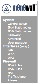
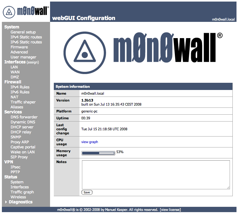
When you first access the m0n0wall webGUI you will see the System Status screen. Along the left hand side of all screens is a menu to allow you to navigate to other screens. The items under the Interfaces menu heading may be different in your system, depending on how many network interfaces you have and how you have named them. The descriptions in the following sections are organized in the same way as the items in the navigation menu.
Note
Some of the screen shots in the following sections include blurred areas. When you view your m0n0wall screens, these will contain information specific to your system.
The General Setup screen allows you to control some general parameters of your firewall.
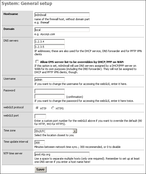
The General Setup screen allows you to change the following parameters:
Table 4.1. General Setup parameters
| Parameter | Description | Example | Reference |
|---|---|---|---|
| Hostname | The unqualified hostname of your firewall. | myfirewall | IP Basics |
| Domain | The domain name to qualify your firewall hostname. | example.com | IP Basics |
| DNS Servers | The IP address of one or more DNS servers for use by the firewall. | 10.0.0.123 | DNS |
| Username | The username to use when connecting to the m0n0wall webGUI. | admin | |
| Password | The password to use when connecting to the m0n0wall webGUI. The current password is not displayed; this field is used only to change the password You should change this when you first install m0n0wall. | ||
| webGUI Protocol | The protocol for the m0n0wall webGUI to use. If you select HTTPS, you will need to securely access your webGUI using a URL that starts with "https:" and to enter a signed certificate and key in the Advanced System page. | ||
| webGUI Port | The port for the m0n0wall webGUI to use, if not the default. | ||
| Time zone | The time zone of your firewall. This affects the value of times printed to logs. | Logging | |
| Time update interval | How often your firewall should contact the NTP server to update its time. | Logging | |
| NTP time server | The name of the NTP (Network Time Protocol) server for your firewall to use. | Logging |
Static routes are necessary when you have a subnet behind another router on any of your internal networks. Static routes are never required for directly connected networks or if the network in question is reachable through your WAN interface's default gateway.
The Static Routes sub section allow the user to set up static routes in order to reach network that must use a gateway different from the default one. By pressing the + icon, the system allows the user to add new static routes.
The parameters to set up a new route are the following:
Interface: select the interface to which the route must be applied. This is the interface off of which the destination network is located.
Destination Network: select the network that have to be reached with Classless Inter-Domain Routing (CIDR) code for subnetting (see RFC1517, RFC1518, RFC1519, RFC1520 for more details)
Gateway: the IP address of the router/gateway that the firewall must use in order to reach the defined Destination Network
Description: enter an optional description for the inserted route
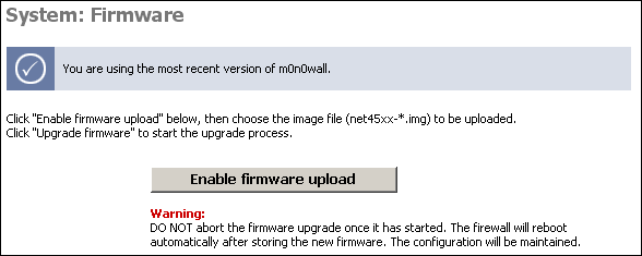
The Firmware screen allows you to upgrade or downgrade your m0n0wall version (only available if you are running a hard drive or compact flash installation).
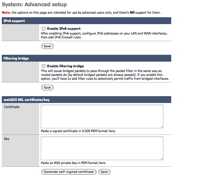
The options on the Advanced System page are intended for use by advanced users only, and there's NO support for them.
Table 4.2. Advanced System Options
| Options | Description |
|---|---|
| IPv6 tunneling | Add the IP address to NAT encapsulated IPv6 packets (IP protocol 41/RFC2893) to here. Don't forget to add a firewall rule to permit IPv6 packets! |
| Filtering bridge | This will cause bridged packets to pass through the packet filter in the same way as routed packets do (by default bridged packets are always passed). If you enable this option, you'll have to add filter rules to selectively permit traffic from bridged interfaces. |
| webGUI SSL certificate/key | Paste a signed (firmware 1.2) or create a self signed (firmware 1.3b12+) certificate in X.509 and a RSA private key in PEM format here. |
| Console menu | Changes to this option will take effect after a reboot. |
| Firmware version check | This will cause m0n0wall not to check for newer firmware versions when the System: Firmware page is viewed. |
| IPsec fragmented packets | This will cause m0n0wall to allow fragmented IP packets that are encapsulated in IPsec ESP packets. |
| IPsec DNS check interval (firmware 1.3) | If at least one IPsec tunnel has a host name (instead of an IP address) as the remote gateway, a DNS lookup is performed at the interval specified here, and if the IP address that the host name resolved to has changed, the IPsec tunnel is reconfigured. The default is 60 seconds. |
| TCP idle timeout | Idle TCP connections will be removed from the state table after no packets have been received for the specified number of seconds. Don't set this too high or your state table could become full of connections that have been improperly shut down. The default is 2.5 hours. |
| Hard disk standby time | Puts the hard disk into standby mode when the selected amount of time after the last access has elapsed. Do not set this for CF cards. |
| Navigation | Keep diagnostics in navigation expanded. |
| Static route filtering | This option only applies if you have defined one or more static routes. If it is enabled, traffic that enters and leaves through the same interface will not be checked by the firewall. This may be desirable in some situations where multiple subnets are connected to the same interface. |
| webGUI anti-lockout | By default, access to the webGUI on the LAN interface is always permitted, regardless of the user-defined filter rule set. Enable this feature to control webGUI access (make sure to have a filter rule in place that allows you in, or you will lock yourself out!). Hint: the "set LAN IP address" option in the console menu resets this setting as well. |
| IPsec SA preferral | By default, if several SAs match, the newest one is preferred if it's at least 30 seconds old. Select this option to always prefer old SAs over new ones. |
| Device polling | Device polling is a technique that lets the system periodically poll network devices for new data instead of relying on interrupts. This can reduce CPU load and therefore increase throughput, at the expense of a slightly higher forwarding delay (the devices are polled 1000 times per second). Not all NICs support polling; see the m0n0wall homepage for a list of supported cards. |
| Firewall states displayed | Maximum number of firewall state entries to be displayed on the Diagnostics: Firewall state page. Default is 300. Setting this to a very high value will cause a slowdown when viewing the firewall states page, depending on your system's processing power. |
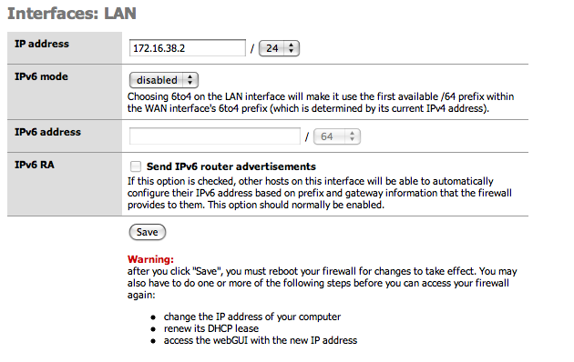
IPv6 support is included in the latest 1.3beta release (v12 or later). The base for this was actually contributed by Michael Hanselmann way back in 2005, and with some modifications to reflect the changes in m0n0wall since then, as well as a few fixes/ improvements (most notably easy to configure 6to4 support), it is now finally in an official release. (Belated) Thanks, Michael!
IPv6 support must be explicitly enabled on the System: Advanced setup page before any of the new options will become available. Also, by default there are no firewall rules for IPv6, so everything is blocked. Make sure to add at least a rule on your LAN interface for outbound connections if you want to use IPv6.
After IPv6 is activated, additional options will become available in the main menu for routing and firewall management. Interface pages will also offer additional IPv6 configuration options. A useful option under the LAN interface will appear to send IPv6 Router Advertisements. This allows other hosts on the LAN to automatically configure their IPv6 address based on the prefix and gateway information that the Firewall provides them.
Caution
Since 1.3b12 is the first release with IPv6 support, bugs in the implementation are likely. As always, please post on the mailing list or in the forum if you've found something odd (with a detailed description of what you did, please). Also let us know if everything worked "out of the box". :)
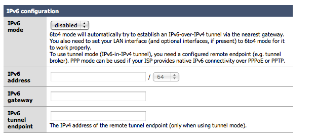
If you don't have native IPv6 connectivity yet, don't worry: 6to4 tunneling is supported, which should work anywhere you've got a (non- firewalled) public IPv4 address. Simply choose "6to4" for the IPv6 mode on both the WAN and LAN interfaces - no need to manually configure any IPv6 addresses (check the IPv6 RA option on the LAN interface and your LAN hosts will be able to automatically obtain an IPv6 address). It can also work with dynamic WAN IPv4 addresses (LAN/ OPT IPv6 subnets are adjusted automatically). Note that some operating systems do not use IPv6 when connecting to a host that supports both IPv4 and IPv6 if they are configured with a 6to4 IPv6 address (-> RFC 3484), so use an IPv6-only host (try http://ipv6.m0n0.ch) for browser testing, or simply do a "ping6".
If you've got native IPv6 connectivity (over PPPoE/PPTP with 1.3b13 or later), remember that you'll have to statically route your m0n0wall's LAN subnet from your upstream router - there's no NAT for IPv6 in m0n0wall (and it would be pretty pointless in most cases anyway :).
Also, if you've gotten it to work and need some IPv6 capable web sites to try it out, have a look at http://sixy.ch (or http://ipv6.sixy.ch), a directory of IPv6 enabled web sites.
Note
Although many operating systems support IPv6 by default such as MacOSX 10.4+, Windows Vista and many Linux packages, some systems need it to be activated (such as Windows XP) and some systems may not support it at all (such as the Apple iPhone 2.0 and older versions of Windows). Check your operating system documentation to see if IPv6 is available.
For more information on IPv6 check out some of the following websites.
Additional webGui users can be added here. User permissions are determined by the admin group they are a member of.
Additional webGui admin groups can be added here as well. Each group can be restricted to specific portions of the webGUI. Individually select the desired web pages each group may access. For example, a troubleshooting group could be created which has access only to selected Status and Diagnostics pages.
The Assign sub menu allows to map the symbolic reference LAN and WAN to the physical interfaces that are present on the system. Click on the Save button to apply changes, and remember that a change in this assignment will require a system reboot for the changes to take effect.
In the LAN section, it is possible to change the IP address and the netmask (in CIDR notation) of the firewall internal interface. The system must be rebooted in order to apply the changes as suggested after pressing the "Save" button.
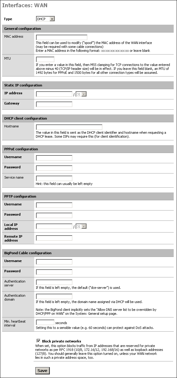
In the WAN sub section, it is possible to set up all the parameters for WAN interface. The WAN Interface can be a Static IP address, a DHCP address, a PPPoE interface or a PPTP connection, as detailed in the following. On the basis of the connection type selected, the related sub panel must be filled.
A detailed description of all the fields follows.
-
Type: the connection type that must be used
Static: A static IP address is assigned to the interface with the related netmask and gateway
DHCP: a dynamic address is assigned to the firewall WAN by a DHCP server on the WAN side
PPPoE: PPP over Ethernet, that is useful for ADSL connection
PPTP: allows to set up PPTP for the ADSL providers that requires this protocol for the connection
-
General Configuration Panel: allow to override default MAC address and MTU
MAC Address: some cable connections require the MAC spoofing. The MAC address must be in the format xx:xx:xx:xx:xx:xx
MTU: the value in this field allows to set up MSS clamping for TCP connections to the value entered above minus 40 (TCP/IP header size). If the field is left blank, an MTU of 1492 bytes for PPPoE and 1500 bytes for all other connection types will be assumed
-
Static IP Configuration: in this panel the static IP and gateway for WAN interface must be set:
IP Address: the static IP with related netmask is set in this field
Gateway: the default gateway for the firewall in set in this field
-
PPPoE Configuration: The Username and password for the ADSL connection should be set up there
Username: the username the provider assign to your connection
Password: the password the provider assign to your connection
-
PPTP Configuration: the parameters inserted in this sub panel allows the user to establish the tunnel required by the PPTP ADSL connection
Username: the username the provider assign to your connection
Password: the password the provider assign to your connection
Local IP Address: the local IP address the provider assign to your connection
Remote IP Address: the remote IP address the provider assign to your connection
Block Private Networks - This option puts in rules to drop traffic coming in on the WAN from private IP subnets. If you configure your m0n0wall with the WAN interface on a private subnet of another LAN, for example, you need to disable this option. Also, some ISP's assign customers private IP's, in which case you'll also need to disable this option
Note
You do not need to disable the Block Private Networks option if you are using IPsec VPN tunnels with private IP addresses. When the VPN packets come into the WAN interface, they will be coming from source IP of the WAN interface of the remote VPN device, not from the private IP subnet on the remote side.
Optional interfaces can be used for a variety of purposes. Generally they are used as second LAN interfaces or DMZ interfaces.
The wireless interface configuration screen is only presented if a compatible wireless card is found at system startup. Options will be presented depending on the features supported for the wireless card. See the Wireless chapter for more information on wireless configuration options.
This service allows you to use the fixed IP address of your m0n0wall's LAN ethernet interface to resolve/proxy all DNS queries on your LAN network. When the m0n0wall DHCP server assigns IP addresses, it also assigns the LAN IP address as the DNS server to use. Otherwise, to benefit from this service you must manually configure the DNS IP address on your computers to be the LAN IP of your m0n0wall.
If the DNS forwarder is enabled, the DHCP service (if enabled) will automatically serve the LAN IP address as a DNS server to DHCP clients so they will use the forwarder. The DNS forwarder will use the DNS servers entered in System: General setup or those obtained via DHCP or PPP on WAN if the "Allow DNS server list to be overridden by DHCP/PPP on WAN" is checked. If you don't use that option (or if you use a static IP address on WAN), you must manually specify at least one DNS server on the System: General setup page.
This is important for instance if you have your DHCP clients renewing their IP address information every 3 days, but every day your WAN IP changes from your ISP. If your ISP changed the DNS servers on you then it would be 2 days until your DHCP clients received the correct information. By using your LAN IP address, all LAN network clients are assured of a working DNS server as long as the m0n0wall has received a good DNS IP address to use... even if it just received the new DNS information a minute ago. This also allows a network administrator to easily redirect all traffic to a new internal DNS server (maybe while transitioning a new server into the network).
Setting "Allow DNS server list to be overridden by DHCP/PPP on WAN" is necessary if your ISP might change the IP address of the DNS server. If you have a static IP address on your WAN than you would not need this option set
The DNS forwarder screen contains configuration options relevant to the DNS forwarding server on your m0n0wall.
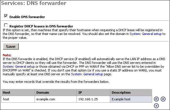
Enabling the DNS Forwarder Check the first checkbox, "Enable DNS forwarder", to enable the service on the LAN interface. After enabling this, you will need to configure your client machines to use the LAN IP address of your m0n0wall as their DNS server.
DNS Host Name Registration
If your m0n0wall acts as the DHCP server for your LAN, and you need name resolution between hosts on the LAN, check the "Register DHCP leases in DNS forwarder" box. It will append the default domain in System:General setup to the host name of the computer that is requesting a DHCP lease. For example, if your machine name is my-pc and your default domain is example.com, it will register my-pc.example.com with the IP address assigned from DHCP, so the other hosts on your LAN can locate your machine by that name.
Caution
Be sure that your computers have unique names.
DNS Forwarder Overrides
If there are certain DNS host names you want to override for your internal DNS clients, add them under DNS overrides on this page. For example, if you want www.yourcompany.com to point to a different site internally than it does from the Internet, enter an override for www.yourcompany.com with the appropriate IP address. This can also be used as a rudimentary (and easy to bypass) filter on web sites LAN clients can visit, by assigning the undesired host name to an invalid IP address. For example, to block www.example.com, put in an override to redirect it to an invalid IP address, such as 1.2.3.4. Note that using a different DNS server or editing the hosts file on the client machine gets around this restriction, but doing this is sufficient to block the site for the vast majority of users.
Dynamic DNS allows you to have a permanent host name that can be used to access your network, generally used when your public IP address is assigned by DHCP and subject to change. This allows you to run your own web server, mail server, etc. using a DNS host name.
For links to providers of dynamic DNS services, visit the website of the dynamic DNS client used by m0n0wall, ez-ipupdate.
After you have signed up with one of the dynamic DNS providers listed, you can continue.
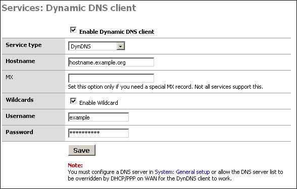
Configuring the Dynamic DNS Client
To start, first check the "Enable Dynamic DNS client" box at the top of the page.
In the "Service type" drop down box, select the service you signed up with above.
Some services support MX DNS records on dynamic DNS subdomains. This helps ensure you can get email to your host name. If your service supports this (dyndns.org is one that does, others do as well), fill in your mail server's host name in that field. If you do not need an MX record or if your provider does not support them, just leave the field blank.
Wildcards - If you want to enable wildcard on your dynamic DNS host name, check this box. This means all host names not specifically configured are redirected to your dynamic DNS name. So if your dynamic DNS is example.homeip.net, and you enable wildcards, www.example.homeip.net, mail.example.homeip.net, anything.example.homeip.net, etc. (i.e. *.example.homeip.net) will all resolve to example.homeip.net.
The next two boxes are for your username and password. Enter your account information from the dynamic DNS provider.
Click Save. Your dynamic DNS host name should immediately be updated with your WAN IP address. To verify this, ping your dynamic DNS host name. It should resolve to the IP address of the WAN interface of your m0n0wall. If not, check Diagnostics: System logs for information on why it failed.
This screen allows you to enable the DHCP server on enabled Ethernet interfaces other than WAN.
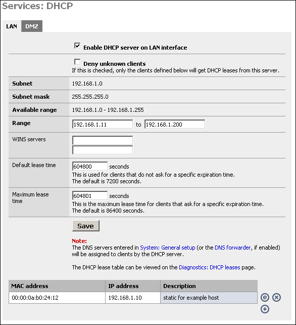
Enabling the DHCP Server
To enable the DHCP server on a particular interface, click on the appropriate tab for the interface and check the "Enable DHCP server on interface" box.
Deny unknown clients
This option allows you to implement a more secure DHCP configuration. Many companies suffer from worm outbreaks and related security issues due to unauthorized machines being plugged into their network. This option will help ensure only authorized hosts can receive a lease from your DHCP server. With this option enabled, only hosts defined at the bottom of this page will receive a lease from DHCP.
The downside to this option is that it can be difficult to maintain when you have more than a handful of hosts on your network. Many will find the increased security worth the increase in maintenance. Note that this is only sufficient to stop the typical user that expects to be able to plug into your network and obtain a DHCP lease to get on the Internet. Anyone with network and/or security expertise can easily bypass this.
Subnet, Subnet Mask, and Available range are filled in from the IP and subnet information from that particular interface.
Range
In the first box, enter the starting address of your DHCP range. In the second box, enter the ending address of the range. Note that you don't want to make this the same as the available range, as this includes the subnet address and broadcast address, which are unusable, as well as the address of your m0n0wall interface which also cannot be in the range.
WINS Servers
If you use an NT 4 domain, or have pre-Windows 2000 clients that need to access an Active Directory domain, you will need to fill in your WINS server IP addresses in these boxes. If you only have one WINS server, leave the second box blank.
Default and Maximum Lease Time
The default lease time is the length of the DHCP lease on any clients that do not request a specific expiration time on their DHCP lease. The default is 7200 seconds, or two hours. For the vast majority of network environments, this is too low. I would generally recommend setting this to a week, which is 604,800 seconds.
The maximum lease time must be more than the default lease time. Most networks will not use this value at all. In most instances, I set this to one second longer than the default lease time.
Click Save to save your changes, then click Apply to enable the DHCP server.
Static DHCP Mappings
Static DHCP mappings can be used to assign the same IP address every time to a particular host. This can be helpful if you define access rules on the firewall or on other hosts on your LAN based on IP address, but still want to use DHCP. Alternatively, you can keep the IP address box blank to assign an IP out of the available range, when you are using the "Deny unknown clients" option.
Click the + icon at the bottom of the DHCP configuration page to add a static DHCP mapping.
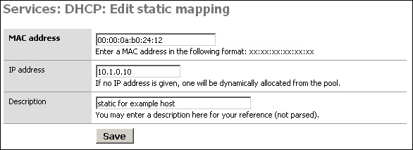
In the MAC address box, fill in the system's MAC address in the format xx:xx:xx:xx:xx:xx. For Windows NT/2000/XP clients, you can get determine the MAC address by opening up a command prompt and typing 'ipconfig'. For Windows 95/98/ME clients, go to Start, Run, winipcfg. For Unix clients, use ifconfig.
In the IP address box, fill in the IP address you want to be assigned to the client, or leave it blank to automatically assign one from the available DHCP range. If you put in a static IP address, it must not be within the range of the DHCP server.
It is recommended you fill in a description in the Description box to remind you what this entry is for, though this is an optional value.
Click Save when you are finished and the mapping will be added.
Note
The DNS servers entered in System: General setup (or the DNS forwarder, if enabled) will be assigned to clients by the DHCP server.
The DHCP lease table can be viewed on the Diagnostics: DHCP leases page.
SNMP is a Network Management Protocol that allows a central management software to consult information on devices running an SNMP agent. You can enable a SNMP agent on your LAN interface on this screen. This is useful if you have a network management or monitoring system that takes advantage of it. This service uses UDP port 161.
Caution
Retrieving information from a m0n0wall SNMP agent is only secured by the community name. All information is transmitted in clear text. If you want additional security you will need to either use filters to limit who has access to this port or access it over an encrypted channel such as PPTP or IPSec.
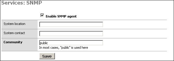
The System location and System contact boxes can be left blank, but can assist you in determining which device you are monitoring if you have several monitored hosts.
The Community is generally set to "public", but if you have any regard for security at all, you should set this to something difficult to guess, containing numbers and letters. This community name is still passed over the network in clear text, so it could be intercepted, though the most anyone could get with that community name is information on the setup and utilization of your firewall. In most environments, this is likely of little to no concern, but is something to keep in mind.
After setting the values as you desire, click Save and your changes will be applied.
Proxy ARP can be used if you need m0n0wall to send ARP replies on the WAN interface for other IP addresses than its own WAN IP address (e.g. for 1:1, advanced outbound or server NAT). It is not necessary if you have a subnet routed to you or if you use PPPoE/PPTP, and it only works if the WAN interface is configured with a static IP address or DHCP.
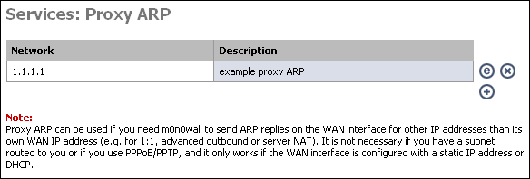
If you enable 1:1, server, or advanced outbound NAT, you may need to enable proxy ARP for the IP address(es) being used by those translations. To do so, click the + on this page.
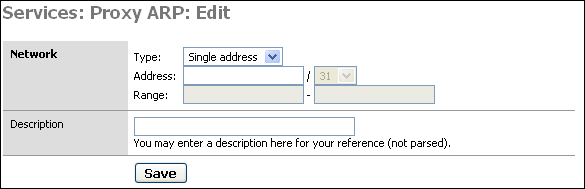
Enter either a single IP address, or subnet or range of addresses, optionally add a description to remind you why you made this entry, and click Save. Then click "Apply changes" for m0n0wall to enable proxy ARP.
For more information on when you do and do not need Proxy ARP, see this page.
What is Captive Portal? from wikipedia.org
The captive portal technique forces a HTTP client on a network to see a special web page (usually for Authentication) before surfing the Internet normally. This is done by intercepting all HTTP traffic, regardless of address, until the user is allowed to exit the portal. You will see captive portals in use at most Wi-Fi hotspots. It can be used to control wired access (e.g. apartment houses, business centers, "open" Ethernet jacks) as well.
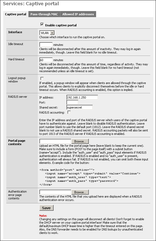
Check the "Enable captive portal" box to enable.
Interface - Select the interface on which you want to enable captive portal. It can only run on one interface at a time.
Idle timeout - Clients will be disconnected after this amount of inactivity. They may log in again immediately, though. Leave this field blank for no idle timeout.
Hard timeout - Clients will be disconnected after this amount of time, regardless of activity. They may log in again immediately, though. Leave this field blank for no hard timeout (not recommended unless an idle timeout is set).
Logout popup window - If enabled, a popup window will appear when clients are allowed through the captive portal. This allows clients to explicitly disconnect themselves before the idle or hard timeout occurs. When RADIUS accounting is enabled, this option is implied.
Note
Most any popup stopper will block this window. Worse, you cannot exclude a specific site, as this popup appears to come from whatever server the user tried to go to prior to authentication. If you have a popup blocker, you'll need to disable it prior to logging in, and then re-enable it after the log off popup appears.
RADIUS server - Enter the IP address and port of the RADIUS server which users of the captive portal have to authenticate against. Leave blank to disable RADIUS authentication. Leave port number blank to use the default port (1812). Leave the RADIUS shared secret blank to not use a RADIUS shared secret. RADIUS accounting packets will also be sent to port 1813 of the RADIUS server if RADIUS accounting is enabled.
Portal page contents - Here you can upload an HTML file for the portal page (leave blank to keep the current one, or the default if you have not uploaded one previously).
Authentication error page contents - The contents of the HTML file that you upload here are displayed when a RADIUS authentication error occurs (generally because of an incorrect logon or password).
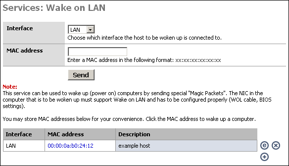
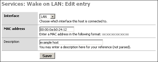
This service can be used to wake up (power on) computers by sending special "Magic Packets". The NIC in the computer that is to be woken up must support Wake on LAN and has to be configured properly (WOL cable, BIOS settings).
This might be useful, for instance, if you access your home or corporate network remotely via VPN, and need to access a machine that may not be powered on at all times. You can log into the m0n0wall device at that location and send a wake up packet.
To power on a machine, just choose the appropriate interface, put the MAC address of the machine into the MAC address box, and click "Send".
If you use this feature at all, you will probably want to create a list of the machines you want to remotely power on. If you click the + at the bottom of the screen, you can add a host to the list that is displayed. Once you have added the host to your list, you can simply click on the MAC address to power on the system.
A SIP proxy configuration page is available starting in firmware 1.3. This pages activates and configures a SIP proxy/masquerading service. Only use it when other Firewall traversal options like using STUN or outgoing SIP proxy services aren't offered by your SIP service provider. If activated, configure your SIP User Agents (phone) to use this server as outbound proxy.
Table 4.3. SIP Proxy Parameters
| Parameter | Description |
|---|---|
| Enable SIP Proxy | Enable or disable SIP Proxy |
| Interface | Select the interface local to your SIP endpoints like VOIP phones. Usually your LAN port. |
| SIP UDP port | Default UDP port is 5060. If left at default, this proxy also acts as transparent proxy by redirecting outgoing SIP messages to this SIP proxy. |
| RTP UDP port range | A port range large enough to hold multiple concurrent calls. Each audio call needs 2 ports, each video call needs 4 ports. |
When enabled on port 5060, all outgoing SIP messages are redirected to this SIP proxy. Firewall rules are added automatically to the WAN interface for the UDP SIP signaling and UDP RTP streams to be reachable from the outside world. It is possible to use this service as a very simple SIP registrar (without authentication, but limited to the local LAN subnet). Use the same server for registration and outbound proxy.
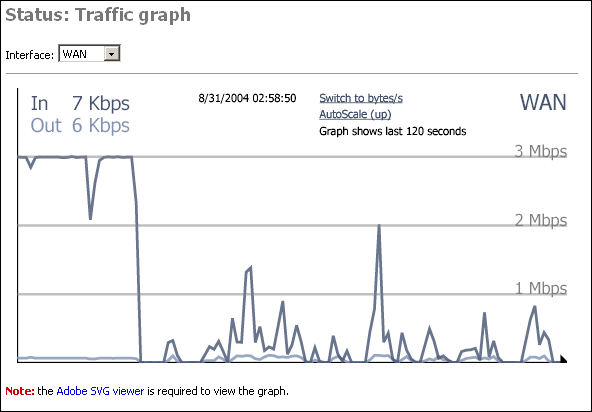
The traffic screen allows you to select an interface, and view real time throughput graphs on that interface. This feature was introduced in version 1.1.
The Adobe SVG viewer is required to view the graphs. This page has a link to the installation for this viewer.
The ultimate page showing the status of your m0n0wall device is actually not shown on the menu. You simply add "/status.php" after the ip address of your m0n0wall device, for example http://10.0.0.1/status.php. This page will show statistics of the following information.
Warning
Make sure to remove any sensitive information (passwords, maybe also IP addresses) before posting information from this page in public places (like mailing lists)! Passwords in config.xml have been automatically removed.
System uptime
Interfaces
Routing tables
Network buffers
Network protocol statistics
Kernel parameters
Kernel modules loaded
ipfw show
ipnat -lv
ipfstat -v
ipfstat -nio
ipfstat -6 -nio
unparsed ipnat rules
unparsed ipfilter rules
unparsed IPv6 ipfilter rules
unparsed ipfw rules
resolv.conf
Processes
dhcpd.conf
ez-ipupdate.cache
rtadvd.conf
df
racoon.conf
SPD
SAD
last 200 system log entries
last 50 filter log entries
ls /conf
ls /var/run
config.xml
System logs are available for the following services:
System logs
Firewall
DHCP
Captive Portal
PPTP VPN
SIP (in firmware 1.3 and higher)
Caution
The logs are limited to available RAM and are erased after a reboot. To store logs permanently you should enable the use of a remote syslog server on the Diagnostic Log Settings page.
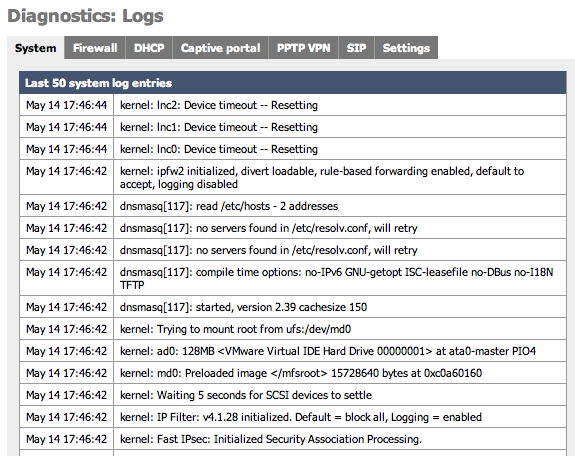
System log (often called syslog) settings can also be configured on this page by clicking on the Settings tab. When sending Syslog to a remote server m0n0wall sends UDP datagrams to port 514 on the specified remote syslog server. Be sure to set syslogd on the remote server to accept syslog messages from m0n0wall and to not block the traffic in any intervening firewalls.
Caution
Because of the detailed information that these messages can contain about your network it is highly recommended to not send syslog messages over the Internet unless they are inside an encrypted tunnel like PPTP or IPSec.
Table 4.4. Log Settings Parameters
| Parameter | Description |
|---|---|
| Show log entries in reverse order | optionally show logs with the newest on top |
| Number of log entries | how many log entries to keep |
| Log packets blocked by the default rule | Hint: packets that are blocked by the implicit default block rule will not be logged anymore if you uncheck this option. Per-rule logging options are not affected. |
| Show raw filter logs | Hint: If this is checked, filter logs are shown as generated by the packet filter, without any formatting. This will reveal more detailed information. |
| Resolve IP addresses to hostnames | Hint: If this is checked, IP addresses in firewall logs are resolved to real hostnames where possible. Warning: This can cause a huge delay in loading the firewall log page! This can often be done by a remote syslog server. |
| Enable syslog'ing to remote syslog server | Activate the use of a remote syslog server to store log messages outside of the m0n0wall device. |
| Remote syslog server | The IP address of remote syslog server and which events should be sent to the syslog server. |
It is recommended that you log your m0n0wall to a remote syslog server for diagnostics and forensic purposes. There are a number of free tools receive and store syslog messages for you on Windows, Mac, and Unix based systems. These software packages also offer additional features such as automatically sending pages, emails or SMS messages as well as running software or commands based on the messages that are received. Some software packages are listed here.
Some operating systems that are by default using syslog messages, such as MacOSX, may have default configurations that limit reception of syslog messages from external sources. If you hav problems receiving messages verify that your syslog server software can receive external messages.
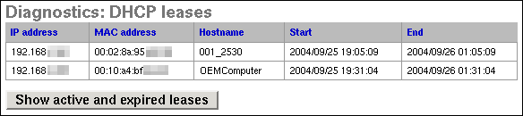
This screen can be used to view your active and/or expired DHCP leases. Clicking the button on this screen will switch between showing only active leases and showing both active and expired leases.
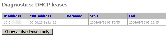
Expired DHCP leases show up in gray text, while active ones are black. (this screenshot from a system with only expired leases)
IPsec maintains two databases with connection details.
Security Association Database
First is the Security Association Database (SAD). This database maintains a list of all current IPsec Security Associations (SA's).
Security Policy Database
Second is the Security Policy Database (SPD). This database maintains a list of all the IPsec policies on the system. You will have two SPD entries for each IPsec VPN connection you have configured, regardless of whether the connection is up. This database tells the system what traffic will pass over VPN, and specifically which tunnel it traverses.
Table 4.5. The two entries for each VPN connection are as follows:
| Source | Destination | Direction | Protocol | Tunnel Endpoints |
|---|---|---|---|---|
| local IP subnet for VPN connection | remote IP subnet for VPN connection | ESP or AH | Public IP address of local m0n0wall - Public IP address of remote endpoint | |
| remote IP subnet for VPN connection | local IP subnet for VPN connection | ESP or AH | Public IP address of remote endpoint - Public IP address of local m0n0wall |
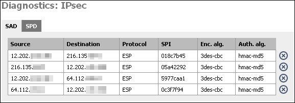
At this screen, you will see two entries for each IPsec connection that has been successfully negotiated. One from the local public IP to the remote endpoint's public IP, and one in the opposite direction. This indicates that IPsec negotiations were successful, and that traffic should now be passing your VPN connection if everything else is configured appropriately.
By clicking on the X, you can delete the SA. m0n0wall will attempt to recreate it after deleting it. If you have a VPN connection with duplicate SA's (more than one from same src to same dst) and the connection has gone down, delete all the SA's associated with the connection. It should renegotiate and come back up within a few seconds.
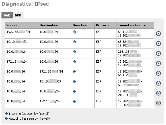
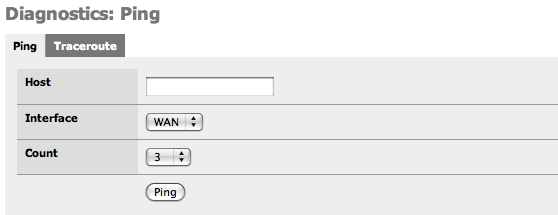
This screen gives you a GUI to ping (send ICMP echo request) from the m0n0wall. Fill in the IP address or hostname of the machine to ping, choose the number of pings in the count drop down, and click the Ping button.
Note
The m0n0wall ping screen cannot ping over VPN connections for the same reason SNMP does not work over VPN out of the box. See this FAQ entry for more information. So do not use this screen as an indicator of whether your VPN is working.
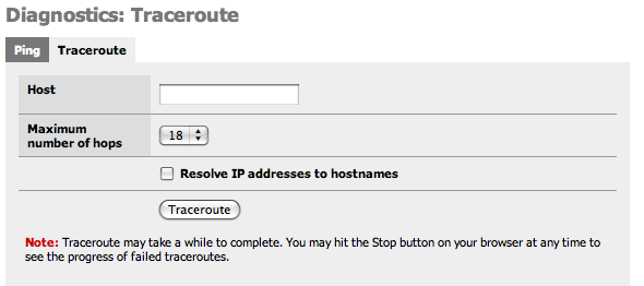
This screen gives you a GUI to traceroute from the m0n0wall. Fill in the IP address or hostname of the machine whose route you want to trace, choose the maximum number of hops in the drop down, and click the Traceroute button.
Note
The m0n0wall ping screen cannot make traceroutes over VPN connections for the same reason SNMP does not work over VPN out of the box. See this FAQ entry for more information. So do not use this screen as an indicator of whether your VPN is working.
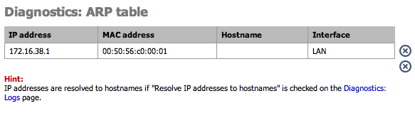
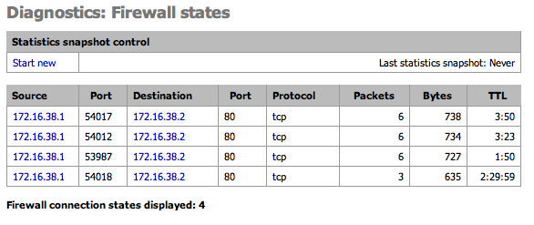
This page shows the current Firewall state table. Optionally take a snapshot of the state stable and compare it to the current table.
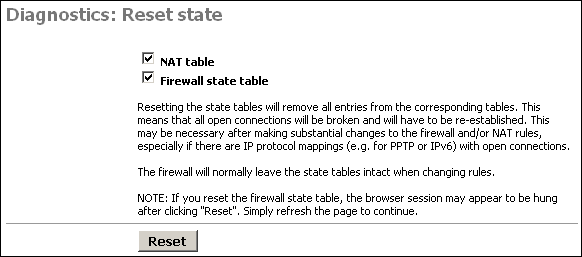
This screen allows you to reset the state tables on your m0n0wall for the NAT and firewall state tables.
Just check the boxes for the table(s) you want to clear, and click the Reset button.
Resetting the state tables will remove all entries from the corresponding tables. This means that all open connections will be broken and will have to be re-established. This may be necessary after making substantial changes to the firewall and/or NAT rules, especially if there are IP protocol mappings (e.g. for PPTP or IPv6) with open connections.
The firewall will normally leave the state tables intact when changing rules.
NOTE: If you reset the firewall state table, the browser session may appear to be hung after clicking "Reset". Simply refresh the page to continue.
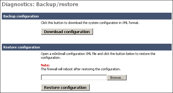
This screen allows you to backup your existing configuration, or restore a previous backup file. These files are text based XML files.
To backup your m0n0wall, click the "Download configuration" button. This will download a file called (by default) config.xml.
If you ever need to restore a previous backup file, go to this page, and under the "Restore configuration" section, click Browse. Locate the config.xml file you backed up above.
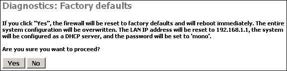
Clicking Yes on this page will reset m0n0wall to the default out of the box configuration options and clear any configuration you have done on the device.
If all else fails when trying to configure something on your m0n0wall, sometimes it is easiest to start over from scratch on the entire configuration. In that instance, use this feature to reload the default settings.
Click Yes on this page to reboot the system.
As a general rule of thumb in m0n0wall and FreeBSD in general, rebooting probably isn't going to fix any problems you are having. But it is worth a shot in many circumstances.
Unlike so many systems, rebooting isn't a suggested maintenance procedure on m0n0wall. There is no need to reboot the system unless you have a specific reason for doing so.
Table of Contents
You may have noticed throughout the webGUI there are some address boxes with a blue background. This blue background indicates you can use aliases in this field. The source and destination boxes on the Firewall Rules Edit screen are two examples of this.
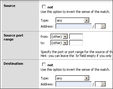
Aliases act as placeholders for real IP addresses and can be used to minimize the number of changes that have to be made if a host or network address changes. You can enter the name of an alias instead of an IP address in all address fields that have a blue background. The alias will be resolved to its current address according to the defined alias list. If an alias cannot be resolved (e.g. because you deleted it), the corresponding element (e.g. filter/NAT/shaper rule) will be considered invalid and skipped.
Go to the Firewall -> Alias screen and click the
![]() to add an alias.
to add an alias.
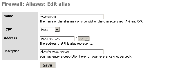
Name: The name of the alias - you'll use this in the blue boxes throughout the system.
Type: Either a reference to a single host, or a network.
Address: This is the IP address or subnet that this alias represents.
Description: As always, optional, but recommended.
-
After verifying your entries, click Save, and Apply changes.
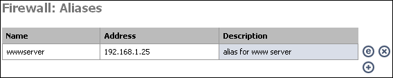
Table of Contents
Network Address Translation (NAT) allows you to use RFC 1918 private IP addresses for addressing on your internal network, and allow all hosts on the internal networks to access the Internet using one public IP address.
Due to the typical expense of obtaining public IP addresses, most networks do not purchase one public IP address for each network host. NAT allows multiple machines to connect to the Internet using a single public IP address. Additionally, using NAT for Internet access protects internal network computers from unwanted access attempts.
Practically, this means that NAT allows you to receive one IP address from your Internet Service Provider and that everyone on your local network can use that IP address to access the Internet. It also allows you to select one or more software services (web server, file server, database server) to make accessible from the Internet but to limit access to other services or IP port numbers.
m0n0wall offers 4 types of NAT:
Inbound NAT
Outbound NAT
Server NAT
1:1 NAT
Caution
Although a NAT rule can redirect traffic into your network you still must enabled filtering rules to allow the traffic to pass through the stateful packet firewall.
There are two most commonly used and most familiar types of NAT, bidirectional or 1:1 (pronounced one to one), and Port Address Translation, or PAT. In both cases m0n0wall will change the IP header of packets that traverse the NAT enabled interface but NAT and PAT each change a different part of the IP header.
NAT translate the IP address in the IP packer header. NAT rules can be applied to TCP or UDP packets that are either incoming and/ or outgoing on any m0n0wall Ethernet interfaces except the LAN interface. Some common NAT uses include:
sharing an Internet connection with multiple computers
adding multiple IP addresses to a WAN interface
translating entire IP subnets to another
redirect outgoing network traffic to a different IP address
redirect incoming network traffic to a different IP address or port address
spoof the IP origin of outgoing traffic to appear as coming from a different IP address
For each NAT rule, m0n0wall builds and maintains a table of network connections that are using each rule.
PAT translates port numbers in the IP packet header. For example you can translate port traffic arriving on the WAN at TCP port 8080 to instead be redirected to port 80. When PAT is combined with NAT you can provide access to multiple webservers such as to send incoming Internet traffic for port 8001 to an internal webserver at 10.0.0.1 port 80 and port 8002 to another web server at 10.0.0.2 port 80.
Note
Since only TCP and UDP packets are using port numbers, only these packets can benefit from PAT based translation rules.
PAT configuration is included in the NAT configuration pages whenever you choose to use port addresses or port ranges. Other uses for PAT include:
hiding common ports to make them less obvious for script based attacks
making data appear to originate from a particular port address
allow multiple instances of a server on the same computer
Normally, an Ethernet interface which has an IP address being requested on a network will respond first to an ARP request to say that the IP address exists and that the Ethernet interface is accepting traffic for it.
Without Proxy ARP you can still assign multiple IP addresses to the WAN interface but your Internet Service Provider must edit their routing tables to redirect the traffic accordingly.
Note
PPPoE connections do not use ARP requests. If you are assigning multiple IP addresses to y PPPoE WAN interface then the service provider must route the traffic correctly.
RFC 1918 - Address Allocation for Private Internets - February 1996
RFC 1631 - The IP Network Address Translator (NAT) - May 1994
Inbound NAT allows you to open up TCP and/or UDP ports or port ranges to hosts on networks protected by m0n0wall. You may need to open ports to allow certain NAT-unfriendly applications and protocols to function properly. Also if you run any services or applications that require inbound connections to a machine on your internal network, you will need inbound NAT.
Inbound traffic is incoming data that arrivs on the selected m0n0wall NAT interface that has not already travelled througn th m0n0wall itself. For example, inbound traffic on the WAN interface coming directly from the Internet can have inbound rules applied to it but traffic from the LAN network that goes through the WAN interface cannot have inbound rules applied because that traffic had to pass through the m0n0wall to arrive at the WAN interface.
Caution
It is not possible to access NATed services using the WAN IP address from within LAN (or an optional network). Only external traffic incoming on the selected interface will have Inbound NAT rules applied to it.
By default, m0n0wall automatically adds NAT rules to all interfaces to NAT your internal hosts to your WAN IP address for outbound traffic. The only exception is for any hosts for which you have configured 1:1 NAT entries. Therefore, if you are using public IP addresses on any of the interfaces behind your m0n0wall you need to change m0n0wall's default NAT behavior by enabling advanced outbound NAT.
If you are using public IP addresses on all the interfaces behind your m0n0wall, check the "Enable advanced outbound NAT" box and click Save. Now nothing will be NATed by m0n0wall.
If you have a public IP subnet off one of your interfaces behind m0n0wall and a private IP subnet behind another interface, you will need to enter your own NAT mappings on this screen. For example, if you have a LAN subnet of 192.168.1.0/24 and a DMZ subnet with public IP addresses, you will need to enable advanced outbound NAT, and click the plus at the bottom of this tab to add a NAT mapping for your LAN network. For this scenario, you will want to add a rule for interface WAN, source 192.168.1.0/24, destination any, target box blank, and enter a description of your choosing.
Note
If advanced outbound NAT is enabled, no outbound NAT rules will be automatically generated anymore. Instead, only the mappings you specify will be used. With advanced outbound NAT disabled, a mapping is automatically created for each interface's subnet (except WAN) and any mappings specified on the Outbound NAT screen will be ignored. If you use target addresses other than the WAN interface's IP address, then depending on the way your WAN connection is setup, you may also need proxy ARP.
Server NAT gives you the ability to define extra IP addresses, other than the WAN IP, to be available for Inbound NAT rules. This can be used to allow two or more IP addresses to be accessible from the selected network interface.
Note
Depending on the way your WAN connection is setup, you may also need proxy ARP.
1:1 NAT maps one public IP address to one private IP address by specifying a /32 subnet. This means having an otherwise local network computer accessible from the Internet through the WAN interface of your m0n0wall device. From a security perspective this also means that all traffic arriving at the WAN interface is forwarded into your network to the designated internal server. Be sure that you have secured the internal server.
Additionally entire subnets can be passed through the NAT. This could be used for situations when multiple connected networks are using the same subnet, such as two sites using a 10.0.0.0/8 subnet.
Note
Depending on the way your WAN connection is setup, you may also need proxy ARP.
So by now you may be thinking "so what kind of NAT do I need?", to which the answer is "it depends."
If you do not make any of your internal servers available to the Internet then you do not need anything more than the default Outgoing NAT. This allows all of the computers on your network to share the single IP address that is assigned by your Internet Service Provider.
If you will be publishing on or more internal servers on the Internet and only have one public IP, the only option is Inbound NAT, since that public IP will be assigned to m0n0wall's WAN interface.
For networks with multiple public IP addresses, the best choice is either 1:1 NAT, or Server and Inbound NAT, or a combination of both. If you have more servers than public IP addresses, you will need to use Server and Inbound NAT, or 1:1 NAT combined with Server and Inbound NAT. If you have sufficient public IP addresses for all of your servers, you should use 1:1 NAT for them all.
Inbound and Server NAT is most suitable when you have more servers than public IP addresses. For example, if you have three servers, one HTTP, one SMTP, and one FTP, and have only two public IP addresses, you must use Server and Inbound NAT. For small deployments, this isn't bad to deal with. As the number of hosts increases, things get far more complicated. You'll end up having to remember things like for public IP address 1.2.3.4, port 80 goes to server A, port 25 goes to server B, port 21 goes to server C, etc.
If you are using software applications that open many rrandom ports to the Internet, such as certain video/voice IP software, you might need to use 1:1 NAT to be sure that whatever port is needed can get through to your computer.
If you can't clearly picture a network in your head while troubleshooting problems, things become much more difficult. With ports going all over the place like this, once you get a number of ports forwarded it's extremely difficult to picture the network in your head. Given the complexity introduced by such a configuration, we recommend having one public IP address per publicly-accessible host.
m0n0wall's traffic shaper uses FreeBSD's dummynet and ipfw. Little documentation on the traffic shaper exists because Chris Buechler, author of the majority of this documentation, has not taken the time to figure it out to the extent that it can be documented. Documentation contributions would be much appreciated. Please email any contributions to Chris.
Suggested Resources
Adam Nellemann's "Traffic shaper 'manual' (alpha)" post to the mailing list back in February 2004 is the closest thing to any traffic shaping documentation that is currently available.
Resources on ipfw and dummynet may be useful, for the information they provide on pipes and queues.
Dummynet paper from the Philippines Department of Science and Technology
BSDnews Using Dummynet for Traffic Shaping on FreeBSD (not currently available)
The following from the dummynet man page may also be helpful.
dummynet operates by first using the firewall to classify packets and
divide them into flows, using any match pattern that can be used in ipfw
rules.  Depending on local policies, a flow can contain packets for a
single TCP connection, or from/to a given host, or entire subnet, or a
protocol type, etc.

Packets belonging to the same flow are then passed to either of two dif-
ferent objects, which implement the traffic regulation:

  pipe  A pipe emulates a link with given bandwidth, propagation
         delay, queue size and packet loss rate.  Packets are queued
         in front of the pipe as they come out from the classifier,
         and then transferred to the pipe according to the pipe's
         parameters.

  queue  A queue is an abstraction used to implement the WF2Q+ (Worst-
         case Fair Weighted Fair Queueing) policy, which is an effi-
         cient variant of the WFQ policy.
         The queue associates a weight and a reference pipe to each
         flow, and then all backlogged (i.e., with packets queued)
         flows linked to the same pipe share the pipe's bandwidth pro-
         portionally to their weights.  Note that weights are not pri-
         orities; a flow with a lower weight is still guaranteed to
         get its fraction of the bandwidth even if a flow with a
         higher weight is permanently backlogged.

In practice, pipes can be used to set hard limits to the bandwidth that a
flow can use, whereas queues can be used to determine how different flow
share the available bandwidth.Table of Contents
This chapter will go over configuring a site to site Virtual Private Network (VPN) links between two m0n0walls, discuss how to configure site to site links with third party IPsec-compliant devices and discuss VPN to remote IPSec client software. Once you have IPSec properly configured you will be able to take advantage of the following capabilities:
Support incoming mobile connections (for instance from a laptop)
Connect and encrypt two or more Monowall devices over the Internet (and their local networks)
Communicate with 3rd party IPSec capable devices (Cisco, Checkpoint and others)
The Example VPN Configurations chapter goes over, in detail, how to configure site to site IPsec links with some third party IPsec devices. Although it might seem confusing, in most cases you just need to assure that all of the parameters match on both sides (except of course the definition of who is the remote network). Some routing issues might come up depending on your situation but reading the rest of this chapter should be enough to successfully use IPsec encryption.
If you have gotten m0n0wall working in a site to site IPsec configuration with some third party IPsec device that is not already listed, we would appreciate if you could put together a short write up of how you got it configured, preferably with screenshots where applicable.
IPsec (IP security) is an international standard for providing security to IP protocols via encryption and/or authentication, typically employing both. Its use in m0n0wall is for Virtual Private Networks (VPN's). After two or more points securely authenticate each other's identification, access rights, and how to encrypt data (phase 1), they will be able to communicate using encrypted data packets (phase 2). The two points can be on a local network, a wireless network or even on the Internet.
There are two general types of IPsec VPN capabilities in m0n0wall, site to site and remote access. Site to site will connect entire networks while remote access allows mobile users access to secured networks.
The IPsec specification includes many features and services. Below is a list of IPsec features, including features not currently supported by selected m0n0wall versions.
Table 8.1. IPSec Feature List
| Feature | 1.2 | 1.3 | |
|---|---|---|---|
| Site to site | x | x | |
| Mobile user to site | x | x | |
| Tunnel mode | x | x | |
| Transport mode | |||
| Perfect Forward Security (PFS) | x | x | |
| Main Mode | x | x | |
| Aggressive Mode | x | x | |
| Remote gateway hostname/domain support | x | ||
| IKEv2 support | |||
| Phase 1 local IP, Domain, FQDN Identifier | x | x | |
| Phase 1 local RSA Cert Subject Identifier | x | ||
| Phase 1 Authentication Hashes md5, sha1 support | x | x | |
| Phase 1 Authentication Hashes tiger192, ripemd160 support | |||
| Phase 1 Authentication Preshared Key support | x | x | |
| Phase 1 Authentication RSA / PKI X.509 Certificate support | x | x | |
| Phase 1 Authentication DSA Certificate support | |||
| XAUTH Authentication | |||
| Phase 2 Diffie-Hellman Key support 768, 1024, 1536 bit (also Modp) | x | x | |
| Phase 2 Diffie-Hellman Key support 2048, 3072, 4096 bit (also Modp) | |||
| Encryption Ciphers DES,3DES, Blowfish, CAST128 | x | x | |
| Encryption Cipher AES (Rijndael) | x | ||
| Encryption Ciphers Twofish, Serpent, IDEA | |||
| NAT-T Traversal | x | ||
| Dead Peer Detection | x | ||
| IPSec diagnostic logs | x | x | |
| Dynamic DNS remote site support | x | ||
| IPSec Traffic filtering | |||
| DHCP over IPSec | |||
| L2TP Authentication | |||
| Manual Key support | |||
| Certificate Revocation List |
Site to site VPN's connect two locations with static public IP addresses and allow traffic to be routed between the two networks. This is most commonly used to connect an organization's branch offices back to its main office, so branch users can access network resources in the main office. Prior to VPN's, much more expensive private Wide Area Network (WAN) links like frame relay, point to point T1 lines, etc. were commonly used for this functionality. Some organizations are moving towards VPN links between sites to take advantage of reduced costs.
Site to site VPN's can also be used to link your home network to a friend's home network, to provide access to each other's network resources without opening holes in your firewalls.
While site to site VPN's are a good solution in many cases, private WAN links also have their benefits. IPsec adds processing overhead, and the Internet has far greater latency than a private network, so VPN connections are typically slower (while maybe not throughput-wise, they at least have much higher latency). A point to point T1 typically has latency of around 4-8 ms, while a typical VPN connection will be 30-80+ ms depending on the number of hops on the Internet between the two VPN endpoints.
Tip
When deploying VPN's, you should stay with the same ISP for all sites if possible, or at a minimum, stay with ISP's that use the same backbone provider. Geographic proximity usually has no relation to Internet proximity. A server in the same city as you but on a different Internet-backbone provider could be as far away from you in Internet distance (hops) as a server on the other side of the continent. This difference in Internet proximity can make the difference between a VPN with 30 ms latency and one with 80+ ms latency.
m0n0wall provides two means of remote access VPN, PPTP and IPsec (with OpenVPN available in beta versions only for now). m0n0wall's mobile IPsec functionality has some serious limitations that hinder its practicality for many deployments. m0n0wall version 1.2 does not support NAT-Traversal (NAT-T) for IPsec, which means if any of your client machines are behind NAT, IPsec VPN will not work. This alone eliminates it as a possibility for most environments, since remote users will almost always need access from behind NAT. Many home networks use a NAT router of some sort, as do most hot spot locations, hotel networks, etc.
Note
NAT-T is supported in m0n0wall version 1.3 beta.
One good use of the m0n0wall IPsec client VPN capabilities is to secure all traffic sent by hosts on a wireless network or other untrusted network. This will be described later in this chapter.
FIXME - A second limitation is the lack of any really good, free IPsec VPN clients for Windows. Most of your remote users will likely be Windows laptop users, so this is another major hindrance.
For most situations, PPTP is probably the best remote access VPN option in m0n0wall right now. See the PPTP chapter for more information.
IPsec's Tunnel mode is supported on m0n0wall devices. This mode allows secured communication between entire subnets. When the packet leavs the subnet it will be encrypted, when it gets to the remote IPSec device the packets are decrypted and routed/ sent into the remote network.
The IPsec Specification supports a 2nd mode of operation called Transport mode. Transport mode limits encrypted communication to the 2 devices that are encrypting the information. If this was supported it would only allow secured communication to the m0n0wall device itself and not to its connected networks. Transport mode is not supported.
This option increases security during authentication by assuring that new keys (which are generated on a regular basis to ensure security) are not based on previous keys. When activated, this means that if someone obtains or discovers 1 encryption key that they cannot use it to discover previous or future keys. This can be disabled to allow faster key negotiation.
Most operating systems include IPsec clients. Windows 2000 and above includes a free IPsec client but it is also difficult to configure. MacOSX 10.3 and later also includes a free IPsec client but the free configuration tool is for a special version of IPsec called L2TP/IPsec. Free configuration tools exist for both operating systems but commercial solutions, at least for Windows, are more evolved and easier to use than the built-in free version.
Note
m0n0wall does not support L2TP so if your IPsec client software only supports L2TP it will not work with m0n0wall. However, for adventure seekers, there is a how to for using IPsec on a device and L2TP on an internal Windows 200x server to offset the encryption workload: http://koeppe-net.de/l2tp-howto.txt. This has not been tested yet with m0n0wall devices.
Below is a list of IPsec software clients.
shrew - win32 - http://www.shrew.net
the green bow - win32 - http://www.thegreenbow.com
IPsecuritas - MacOSX - http://www.lobotomo.com - howto
Freeswan/ Openswan/ Strongswan - Linux - http://www.strongswan.org
Racoon - Freebsd
Caution
In some versions of Microsoft Windows, you must deactivate the built-in IPsec client before installing a commercial 3rd party IPsec client. Be sure to read the installation instructions.
Most special IPsec features have been added to beta versions of m0n0wall and may be changed or withdrawn before a final stable version release.
Starting in firmware 1.3b11 it is possible to configure a Dead Peer Detection (DPD) interval in seconds with a default of seconds. This allows the m0n0wall device to detect if a tunnel is still being used. If the DPD interval has passed and the m0n0wall devices finds an IPsec tunnel is not exchanging phase 1 IKE messages (which should be happening even if the tunnel is not being used to transmit data) the tunnel will be closed.
Without this option activated, an IPsec tunnel may be left open and active when an actual problem has appeared such as bad routing, reboot of the remote client, change of IP addresses.
Both sides of the IPsec connection must support and activate Dead Peer Detection.
Note
Firmware 1.3b11 also includes a fix for m0n0wall preferring new SAs over old SAs by default (should solve problems with tunnels not working after an interruption or peer IP address change). In previous versions old SAs where preferred.
Starting in firmware 1.3b6 it is possible to configure domain names to be IPsec connection endpoints. Although fixed IP addresses are recommended for building IPsec connections, using domain names allows IPsec usage with clients whose IP address may change frequently (a home Internet connection or a laptop user at a wireless hotspot for example.)
The IPsec DNS Check Interval option is under the System > Advanced menu. An interval time in seconds can be set here. If at least one IPsec tunnel has a host name (instead of an IP address) as the remote gateway, a DNS lookup is performed at the interval specified here, and if the IP address that the host name resolved to has changed, the IPsec tunnel is reconfigured. The default is 60 seconds.
The remote connection point must use a Dynamic DNS client software that registers any IP address changes with the domain server.
Starting in firmware 1.3b2 it is possible to use NAT Traversal (NAT-T) with IPsec connections. This feature allows IPsec clients to be behind a NAT device (common in a home or office firewall). Using ESP packets to transmit encrypted data does not allow it to pass through a NAT transformation but encapsulating the encrypted data in UDP packets allows the data to pass through NAT transformations.
Using NAT-T creates two types of traffic: IKE authentication (phase 1) on UDP 500 and encrypted data (phase 2) on UDP 4500. These two ports must be allowing data on the m0n0wall device and not be blocked by any intervening firewalls. This feature can be turned on or off for each IPsec connection.
Starting in firmware 1.3b6 there is firewall support for decapsulated IPsec packets (new pseudo-interface "IPsec" in firewall rule editor); this is on by default, but the default configuration contains a "pass all" rule on the new IPsec pseudo- interface (and this is also added automatically for existing configurations), which can then be deleted to actually filter IPsec VPN traffic.
To configure filtering on IPsec traffic, select the IPsec interface from the list of interfaces that packets must come in to match the selected rule.
Note
These rules are applied to all IPsec connection traffic. The only way to apply rules to specific connections is to additionally use a source IP address or subnet that is used on a selected remote IPsec connection.
Before getting started, you need to take care of the following.
Your m0n0wall must be setup and working properly for your network environment.
-
Both locations must be using non-overlapping LAN IP subnets.
i.e. if both sites are using 192.168.1.0/24 on the LAN, no site to site VPN will work. This is not a limitation in m0n0wall, it's basic IP routing. When any host on either of your networks tries to communicate with 192.168.1.0/24, it will consider that host to be on its local LAN and the packets will never reach m0n0wall to be passed over the VPN connection. Similarly, if one site is using, for example, 192.168.0.0/16 and one using 192.168.1.0/24, these subnets are also overlapping and a site to site VPN will not work.
Keep in mind the more networks you link together the more important this basic fact becomes. Do not use unnecessarily large subnet masks. If you setup your LAN as 10.0.0.0/8, but only have 100 hosts on it, you're unnecessarily limiting your ability to add VPN networks anywhere in the 10.x.x.x space.
If m0n0wall is not the default gateway on the LAN where it is installed, you must add static routes to whatever system is the default gateway, pointing the remote VPN subnet to the LAN IP of m0n0wall.
You will need to either control or be in contact with the person who does control the other VPN concentrator. If it is another m0n0wall system, then share this document with the other administrator. If it isn't then have them consult the documentation that came with the IPsec device they are using.
-
Decide how much you trust connected users and/ or networks.
Host and application level security become more important when connecting multiple networks, how much depending on how much you trust the other network. The VPN tunnel will not respond to firewall rules at the time of this writing, so you will not be able to limit which hosts can be accessed by users across the VPN connection. If a worm would get into the network you are connected to via VPN, it could easily spread to your network. If a system on the remote network is compromised by an attacker, he could easily hop over the VPN to attack your systems without any firewall protection.
-
Pay attention to what you are doing!
If you have a VPN to your office, and a VPN to your friend's home network, your friend can now hop over to your company's network from your network. Or, if your friend gets infected with a worm, it could then infect your machines and continue to propagate over the VPN connection to your office. Most companies would probably fire you if your friend was caught on their network. Best bet here is if you have a site to site VPN into your network at work, do not connect with friends, or use one network and firewall for accessing work and one for accessing your friend's network.
Ok now that we have the basics let's get started on the m0n0wall settings.
Log into your m0n0wall and click IPsec , under VPN.
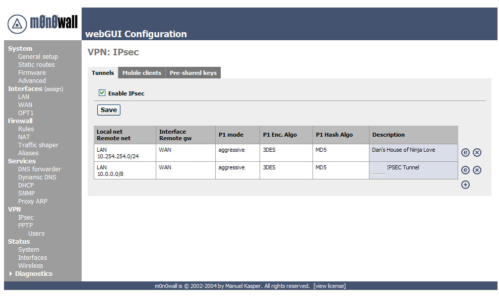
Ok now we need to add a VPN connection, to do this click on the
![]() icon.
icon.
You will be presented with a great form, I will be pasting screen shots of each section as we discuss it.
The first area is the one you use to establish what network ranges will use this IPsec tunnel.

This is the first set of fields that we need to concentrate on. Later, when testing your tunnel, you can actually fail to establish level 2 connection if this data is incorrect. I will note what to pay particular attention to as we go along.
Mode, this is a hard set option and frankly you don’t need to change it (nor can you.)
Disabled, this is a great “on / off” button if you need to disable the tunnel for what ever reason. Simply select the edit or
 from the main VPN: IPsec window and click this
checkbox element, then select apply at the bottom of the page. When
you need the tunnel again, reverse the process.
from the main VPN: IPsec window and click this
checkbox element, then select apply at the bottom of the page. When
you need the tunnel again, reverse the process.Interface, this is how you determine which part of your network will be the termination point (end point) for the VPN Tunnel. If you are connecting to a remote server, then WAN is your option.
Local subnet. This is where you can set which parts, hosts, or the entire LAN can be accessed from the other side of the VPN tunnel. The easiest thing to do is to set the LAN subnet as the option; this means your entire LAN will be accessible from the remote network. IMPORTANT: The other end of the tunnel has this same field, well it probably has 99% of these fields actually, make sure the other end is set exactly as you set this end. E.g. if you said “Single host” in this section and entered the IP address of that host, the other person would set that host in his “Remote Subnet” field. The same goes for you, and with that mentioned we move to the next field.
Remote Subnet. This is more than just labeling which hosts and / or host you want to access on the other network, as mentioned in item 4 it is paramount that you set this exactly like the other end’s “local subnet” section. If not, level 2 of the VPN connection will fail and traffic will not pass from one VPN segment to the other.
Description: It is a good practice to always leave notes about why you are doing something. I suggest you enter something about what this VPN tunnel is used for, or about the remote end of the tunnel to remind yourself who/what it is.
Ok all the basic for the routing have been established. Now we move on to phase 1 of the VPN authentication process.
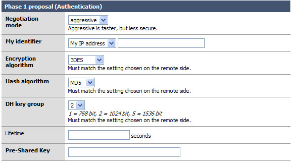
Okay the easy part of the VPN tunnel. The trick here, and even in phase 2, is to make sure that both VPN servers have EXACTLY THE SAME SETTINGS for all of these fields. Well okay, they will have different “My identifier” but make darn sure that they know each others names… more on that later.
Negotiation mode: This is the type of authentication security that will be used. Unless you are under close watch by someone with paranormal like craziness, just leave this as aggressive. It is indeed far faster and will insure that your VPN tunnel will rebuild itself quickly and probably won’t time out an application if the tunnel was down when the resource on the other end was requested. (more about that under Lifetime)
My identifier: This is the key to probably 90% of the email on the list where people seem to not get the VPN tunnel up, or want to know how to do this with dynamic IP addresses, etc. Very simple, set your identifier to something that is not going to change. So if you leave it as My IP address (* This will be the IP address of the “interface” you listed in the first section. *) then make sure that IP is static and persistent. If you use a DHCP assigned address then I would suggest using domain name instead This is because domain name can be completely your own even if you do not own the domain name. Make yours sexylovemonkey.com just for fun. ;)
Encryption Algorithm: 3DES is the world de facto… if you are connecting to another m0n0wall, or a system that will support it, change this to Blowfish. It is a more secure and about twice as fast! Now of course, if you are trying to connect to a VPN device that only supports DES then you will need to downgrade and hope no one decrypts your key exchange. MAKE SURE BOTH VPN DEVICES ARE USING THE SAME ENCRYPTION ALGORITHM.
Hash Algorithm: this is the hash used for checksum. MD5 is a good choice, SHA1 is the new up and comer and it is more reliable then MD5, but not all things support it. Again make sure you are using the same setting as the other end of the tunnel, and if you can use SHA1 go for it!
DH Key Group: Most systems will support at least up to 1024 bit. This is a good place to stick to, going with more will eat up more resources and less makes your tunnel less-secure.
Lifetime: This field is far more important then it appears. This lifetime, as opposed to the one in phase 2, is how long your end will wait for phase 1 to be completed. I suggest using 28800 in this field.
Preshared Key: Contrary to some suggestions this key must be exactly the same on both VPN routers. It is case sensitive, and it does support special characters. I suggest using both. E.x. f00m0nk3y@BubbaLand
Okay if you managed to coordinate and get both VPN systems set the same all should be good for phase 1. We really don’t want to stop here, so let’s go right into phase 2.
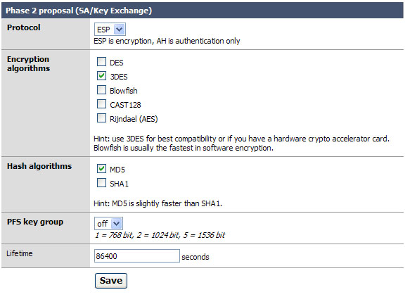
Phase 2 is what builds the actual tunnel, sets the protocol to use, and sets the length of time to keep the tunnel up when there is no traffic on it.
Protocol: ESP is the de facto on what most VPN systems use as a transport protocol. I suggest leaving this as is. Note: The system should auto generate a firewall rule for you to allow ESP or AH to the endpoint of the VPN. We will check this later, if it does not you will need to make a firewall rule allowing ESP (or AH if you changed this) traffic to the interface you established as your end point of the tunnel. I will outline that after figure 5.
Encryption algorithms: Ok here is the deal on this. Like before in phase 1, make sure you are setting the algorithm exactly as it is set on the other VPN server. You can use several; when you do so everything you select is available for use. Honestly I like to keep things simple so I recommend only checking the one you are going to use. With m0n0wall to m0n0wall use Blowfish for speed and security over 3DES.
Hash algorithms: again just as in phase 1 you want to make sure your selected hash matches the one on the other end. And like in step 2, don’t add things you don’t need. SHA1 is the suggestion if you can, but MD5 is always a good alternative.
PFS key group: this works exactly like it does in phase 1. I suggest using 1024 bit, the default is off.
Lifetime: This is the lifetime the negotiated keys will be valid for. Do not set this to too high of a number. E.g. more than about a day (86400) as doing so will give people more time to crack your key. Don’t be over paranoid either; there is no need to set this to 20 minutes or something like that. Honestly, one day is probably good.
Click Save
Click Apply Changes
Below are some possible issues that you may face when building IPSec connections.
FIXME - In some cases you have a firewall or router with layer 2 routing (protocol ACLs) sitting in front of your m0n0wall. If this is the case you will need to port forward ESP or AH (depending on which one you chose) to the m0n0wall. (NOTE: if you are running NAT on that firewall AH will not be an option.)
Starting in m0n0wall firmware 1.3 NAT-T traversal is supported. This allows all ESP packets to be encapsulated in UDP packets using port 4500. Allowing and redirecting UDP 500 traffic (used for IKE authentication in phase 1) and UDP 4500 (NAT-T encapsulated data packets in phase 2) allows the m0n0wall to be placed behind another firewall.
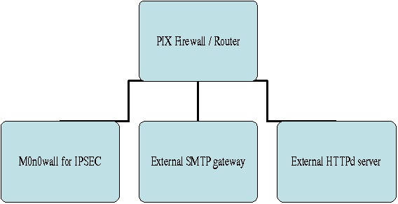
Below are some more issues that you may face when building IPSec connections.
- 8.5.2.1. What if I have a Dynamic DNS name?
- 8.5.2.2. What happens when I change my IPSec configuration?
- 8.5.2.3. Can a single IPsec tunnel support non-contiguous subnets?
- 8.5.2.4. Can I use NAT on a subnet that is on the other side of an IPsec connection?
- 8.5.2.5. Can fragmented packets pass through an IPsec connection?
- 8.5.2.6. What happens when an IPsec connection is restarted with a new IP address?
- 8.5.2.7. When are IPsec connections opened?
- 8.5.2.8. Can I use the Cisco IPsec client to connect to m0n0wall?
- 8.5.2.9. Can I route any traffic over my IPsec connection?
- 8.5.2.10. Can I forward IP broadcasts over an IPsec VPN?
From Lynn Grant, as contributed to the mailing list.
You will need to generate a certificate and a private key for each router. You can do this with OpenSSL, and there are several tutorials on the web about how to do this. A quicker way is to use the XCA program, from Christian Hohnstaedt. It is available here (http://sourceforge.net/projects/xca) as a *nix tarbal or a Windows exe file, and is licensed under a BSD-like license.
First you need to create a Certification Authority (CA) key to use in signing your certificates. Bring up XCA, and click on the "Private Keys" tab, then click the "New Key" button. Give the key a name like "My Company Certificate Authority". Keytype should be "RSA". The default keysize of 1024 is probably about right.
Now click on the "Certificates" tab, and click the "New Certificate" button. On the "Create x509 Certificate" page, select "Create a self signed certificate with the serial 1". Click on the "Subject" tab. For "Internal name" and "Common name", use something like "My Company Certificate Authority". Fill in the other fields at the top of the page (Country code, State or Province -- spelled out, by the way -- Locality, Organisation, Organ. unit, E-mail address). Click on the "Extensions" tab. Set the type to "Certification Authority". Uner "Key Identifier", select "Subject Key Identifier". Click on the "Key Usage" tab and select "Certificate Sign". Click the "OK" button.
Now that you have a certificate signing certificate, you can make certificates for all of your routers.
In XCA, click on the "private keys" tab, then click the "New Key" button. Give the key a name that lets you remember which router it goes to. Keytype should be "RSA", and the default of 1024 bit keysize is probably about right. Click the "Create" button. Do this for each router.
Click on the "Certificates" tab, then click the "New Certificate" button. On the "Source" page, select "Use this Certificate for signing", and select your CA certificate. (This value should be in the field by default.) On the "Subject" page, enter the information for your router. I use the router name as the Internal Name and Common Name. Click on the "Extensions" tab. Set the type to "End Entity" and under "Key Identifier", select "Subject Key Identifier".
Now comes the most important part. In the "subject alternative name" field, put "IP:" followed by the IP address of the interface, for example "IP:10.0.0.1". This must match the IP address of the interface that the VPN goes over; if you have VPNs on the WAN interface, and VPNs to internal routers on the LAN interface, you will need two separate certificates. Click on "OK" to create your certificate. Repeat this for each router.
Now select each router certificate under the "Certificates" tab and click on the "Export" button. Choose a file name. Select "PEM" for the export format and click "OK".
Now click the "Private Keys" tab. Select the private key for each router, and click on the "Export" button. Choose a file name. Select "PEM" for the export format and click "OK". Keep in mind that the key files are the key to the router's identity, so be sure to delete them as soon as your are done setting up the routers.
It is probably best to get your VPN tunnel working in Pre-Shared Key mode first, so you can get any kinks out of the other parameters, before you add the additional complexity of certificates. Bring up the VPN:IPSEC:Edit Tunnel page on your M0n0walls. If you already have the tunnel working in Pre-Shared Key mode, you can bring them up side-by-side in two browser windows, which will make things easier. Just be sure to move slowly and read all the directions before you do anything, so you don't lose contact with the remote M0n0wall before you get it set up.
Lets say your two routers are RouterA and RouterB. On RouterA, change the "Authentication Method" to "RSA Signature". Bring up the RouterA certificate in your favorite text editor. It should look something like this:
-----BEGIN CERTIFICATE-----
MIIDIzCCAoygAwIBAgIBCTANBgkqhkiG9w0BAQsFADCB0zELMAkGA1UEBhMCVVMx
ETAPBgNVBAgTCElsbGlub2lzMREwDwYDVQQHEwhQYWxhdGluZTEfMB0GA1UEChMW
Q3Jvc3MgRGVzaWduIEdyb3VwIExMQzEfMB0GA1UECxMWQ2VydGlmaWNhdGUgT3Bl
cmF0aW9uczE1MDMGA1UEAxMsQ3Jvc3MgRGVzaWduIEdyb3VwIExMQyBDZXJ0aWZp
LmNvbSAwHhcNMDgxMjI3MTkwMTEzWhcNMDkxMjI3MTIxMzU4WjCBpjELMAkGA1UE
BhMCVVMxETAPBgNVBAgTCElsbGlub2lzMRAwDgYDVQQHEwdDaGljYWdvMR8wHQYD
VQQKExZDcm9zcyBEZXNpZ24gR3QvdXAgTExDMRQwEgYDVQQLEwtUZXN0IHJvdXRl
cjEUMBIGA1UEAxMLVGVzdCByb3V0ZXIxJTAjBgkqhkiG9w0XCQEWFlRlc3RSb3V0
ZXJAZXhhbXBsZS5jb20wgZ8wDQYJKoZIhvcNAQEBBQADgY0AMIGJAoGBAMa+d+T8
Y2F0ZSBBdXRob3JpdHkxJTAjBgkqhkiG9w0BCQEWFnN1cHBvcnRAbmV2YWNyb3Nz
rdr3gomkpeq1Z8gfqXUEehPcZdokA2vMZ9kDykU7IHOlGL5N9dTDIdjmvE6Am4lh
u7mu666PRpLSVK3VALBRK70ycHISOJzs7f2Ixes5SVlfd9r3iRBVQPbtkWIr/xGB
oqSCc6YC7+Tv+c6ElcjwOchlRQWRaL9iYw9XAgMBAAGjMjAwMB0GA1UdDgQWBBQj
g331r3M1BoO6b8Oh+cQVQQOY+zAPBgNVHREECDAGhwQKAAABMA0GCSqGSIb3DQEB
CwUAA4GBAFCXhimp6ISFTBVa8VhJe1tcGioA/T7TrfeeOHtq1z5JPIHate+NqS9L
ZJDT9GsknUq3OVMnCMK5gul+rnIyZaQ2/gof6xMBRtnDkMkm8AiWLaLahoBjfEgL
6mWMh2k/jimSlGuRvrnGgLS+WMkv/w3Ib6f4a01HKFAcma4q2y3z
-----END CERTIFICATE-----
Copy it however your editor does that, and paste it into the "Certificate" box on RouterA's page. Also paste it into the "Peer Certificate" box on RouterB's page.
Now edit the RouterB certificate. Copy it and paste it into the "Certificate" box on RouterB's page and the "Peer Certificate" box on RouterA's page.
Bring up the RouterA private key file in your editor. It should look something like this:
-----BEGIN RSA PRIVATE KEY-----
MIICXQIBAAKBgQDGvnfk/K3a94KJpKXqtWfIH6l1BHoT3GXaJANrzGfZA8pFOyBz
pRi+TfXUwyHY5rxOgJuJYbu5ruuuj0aS0lSt1QCwUSu9MnByEjic7O39iMXrOUlZ
AoGBAJufzdZbHfAWW/tYMCu/vPJyCIl+5fDjZkX4aU1iE/dVBnBLqk+j+coa1eKy
obBsjQuTnTdodk0h8Z8Qxhx14qORA/BTrhGuucdYrTga6VOplxqq4xt1HWzsaD3x
kXGAtXYW0UU/75+nr9a129/aIAEPrBVVwVmyZYbXVZvFXUYxAkEA+ESARUvSKx+9
yqJkZhjFjpHpwgt6V30iYdR6Ve8iSgKlyUTsHthK5SO6PwqRHCymwYEeN2VbPS3e
YTYqfD/EdQJBAMzvGocjfEy/d/TVrj6m7rYtFJTvM2fVhD8KETHBqFSLerm/8T1z
X3fa94kQVUD27ZFiK/8RxaKkgnOmAu/k7/nOhJXI8DnIZUUFkWi9ImMPVwIDAQAB
veB63Cml/CEk08wTBAHMVnhb/P3AZoQNGxsCQQDnl4cMnXkVj0uNjkUX1H3dzBGC
WRCsMmfzWLEyHpwe7C9Y/HlDIMNk0xo3GpVY8fIwylC0nlEpVfN/PXcOZrHNAkA0
RVhy165AtSWXoVkMSe/hL6ZsRobKGT/eBGdWVZrl1Z27+yVBE2B+/VdimB+zJH2R
M9h1zPTRRkVFQ+niDKW5AkAzQAlDlueTOnncxdF4503dUMc6UjXzuPKjioYP3zSI
UVwlxIN74dNw57XP76l1nzFAYeuW9sb4SynmhmxswOE5
-----END RSA PRIVATE KEY-----
Paste it into the "Key" field on RouterA's page. Edit the RouterB private key file, and copy and paste it into the "Key" file on RouterB's page.
Click the "Save" button on each page.
You will now have an "Apply Changes" button at the top of each page. Here is the critical part. As soon as you click either of the "Apply Changes" buttons, you will lose contact with the remote router until the tunnel is re-established. So the proper order is:
Click "Apply Changes" on the remote router's page.
Click "Apply Changes" on the local router's page.
The local router's page should refresh almost immediately. The remote router will take a little longer, since the tunnel has to be re-established, but if you did everything right, it should come up shortly. If the tunnel is slow coming up, you may have to refresh the page if it times out. If something got messed up, like you pasted the wrong certificate in the wrong box, or you got the IP address wrong in the subject alternative key, you will have to change both M0n0wall's back to Pre-Shared Key authentication (which will involve physically going to where the remote router is, since you can't talk to it any more) and start over.
Don't forget to delete the files you exported the private keys to when you are done setting up!
Table of Contents
This chapter is based on Francisco Artes' m0n0wall-PPTP document, used with permission.
This chapter is intended to outline several different PPTP VPN type setups, it includes a how-to on setting up a Windows XP ™ PPTP client to connect to the m0n0wall PPTP VPN server. Later versions of this document will include Linux and other clients.
All Trade Marks ™ are represented in this document, and no intention is made that this document, m0n0wall, or the author are in any way related to any of the companies holding these Trade Marks. All Trade Marks are copy written by their respective companies.
The terms firewall and m0n0wall are used synonymously in this chapter. This is mostly because it is easier to say and type “firewall”.
You need to have a basic understanding of TCP/IP and subnetting to understand this document. The author does make every effort to describe the items being discussed, but let’s face it I can only go so far. (And I did include pictures, which apparently are each worth 1,000 words. So that makes this one HUGE document.)
If you have comments, questions, or suggestions in regard to this
document please email <falcor@netassassin.com>. I will try to
get back to you as quickly as possible, but please do read this document
thoroughly before writing. You may also want to check the
m0n0wall website for email archives on frequently (or
even one-time) questions.
Ok we are going to make several assumptions in this document, if you don’t have these assumptions done already you will need to go get them done before PPTP will work correctly.
Your firewall is already setup to do basic NAT and you have tested this, or at least it is doing what ever kind of routing you wanted it to do.
-
You have configured at least one interface on the firewall so it is working and:
The Client Machine(s) can route to (access) one of the interfaces of your firewall. Make sure of this. If it is an interface that you allow ICMP to access I suggest pinging it.
You have a client machine running some form of VPN client that supports PPTP.
Ok now that we have the basics let’s get started on the firewall settings.
Ok so this isn’t quite true VLAN routing, but we will (quite possibly) be working with a virtual network that doesn’t exist until a PPTP connection is made. If you have a better term for this let me know and I will change it. We are however dealing with some virtual subnets, for instance the “Remote Address Range” will be a /28 and PPTP clients will receive a subnet of 255.255.255.255 (ff.ff.ff.ff for all you HEX people out there.) Just ignore that and trust in the magic of the PPTP Tunnel.
You can select (as you will see later) to set the “Sever Address” and “Remote Address Range” to exist inside of the subnet that you defined for the LAN on the firewall. (e.g. IP Address and subnet bit you set for the LAN under Interfaces LAN on the m0n0wall menu.) Our example uses this setup. Pros and Cons? Well the major pro is that the firewall will allow traffic from this VLAN to route to the WAN (in most cases the Internet.) and it is nice and easy. Con’s, it allows people to rout to the WAN if you don’t want this then read the next paragraph.
You can also setup these two options to have an IP range that is outside of your LAN designation. E.g. LAN = 192.168.1.1/24 (really the 192.168.1.0/24 network) and the PPTP “Server Address” and “Remote Address Range” are set to 192.168.2.254 and 192.168.2.16/28 respectively. This will basically allow those using the PPTP connection to access the LAN, but the firewall will not route traffic for them to the WAN connection. Opt and WiFi networks will also be isolated depending on how you are routing to those networks and if they are in the same network segment (subnet) as the LAN.
Remember, that when you setup a PPTP connection (especially on Windows) all network traffic from that workstation is going to be sent via the PPTP tunnel.
Most people probably skipped right to this point. If you did, it should be easy enough with these examples if you do run into something go read the parts you skipped you may find the answers there you are looking for.
The first thing we want to do is setup the PPTP server. To do this select PPTP from the VPN section of the m0n0wall interface. If you clicked the right thing you will have a screen that looks something like Figure 1.

The next step is to enable the PPTP server. Click the “Enable PPTP server” radio button. (It only gets harder from here.)
Now we have to type. (see harder) So enter the “Server Address” next. This can be an unused IP on your LAN, or another locally usable IP address in a separate subnet. It MUST be in the same networking class as the next entry.
Remote Address range. This is going to be the range of 16 IP addresses that the server will issue to clients. Notice the /28, it is there to remind you there will be 16 hosts. Again, this MUST be in the same subnet class as the IP listed above. (Not in the same /28 though…. If you try to overlap the two the firewall will tell you that you made a mistake.)
In our example we used 192.168.1.254 for the “Server Address” and 192.168.1.192/28 as the “Remote address range.” Think of the “Sever Address” as the default route for the IPs you are going to be issuing to the clients. It is also the virtual interface for the PPTP server.
If you are confused here, or in step 3, please go back and read the section named “Subnetting and VLAN routing” as it covered this in more detail.
If you have a RADIUS server of some sort feel free to fill in the next few boxes. I don’t so they are blank on this example and frankly go outside of the scope of this document anyway.
If you are really security conscious, and your client software supports it, check the box to require 128-bit encryption.
Click “Save” We are all done setting up the server. Now let’s setup some users.
If you have a RADIUS server and you set it up in the previous section you can either choose to skip this one, or add users here that will be found and used before the PPTP Server sends a request to the RADIUS server.
For the rest of us, this stage is quite important as we need a user account to authenticate to the PPTP Server.
Click on “users” under PPTP in the VPN section of the m0n0wall interface.
Click the “+” icon and lets fill in some blanks!
Enter a name in the “Username” box.
Enter and then re-enter the password for this account. (You can’t use special characters at the time of this document, just FYI.)
Click “Save”
When you get back to the next window you will need to click “Apply Settings” NOTE: This will disconnect any active PPTP connections. Being as we are just setting this up for the first time, and this is our first user, let’s hope there aren’t any to disconnect.
If everything went well you should have a screen that looks something like Figure 2.
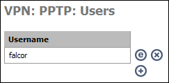
Now we need to setup a firewall rule so people using the PPTP connection can do something with it when they connect.
Yep you need to do this if you want the darn thing to work. But just like your LAN rule, you can make this as open or as restrictive as you want. Here you can limit the PPTP users to accessing only specific hosts on specific ports, or open it all up. We are going to assume you want full access for your PPTP users so we are going to setup a firewall rule that is exactly like the default LAN rule.
Start by clicking “Rules” under the firewall section of the m0n0wall interface.
Next click any of the “+” Icons on the screen so we can add a new rule.
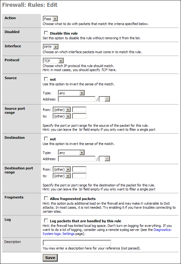
As stated we are going to allow all our PPTP users to access all parts of the LAN, WAN, etc. If you wish to limit this access then you will need to modify things accordingly. I will present one example of such a rule after this default section.
Simply go to the “Interface” section and select PPTP from the drop down. In the Description put something meaningful like “Default PPTP -> any.”
Click Save
You will have to Apply the changes on the next screen.
You are now done setting up the PPTP Server!
In some cases, most for those people who are granting PPTP access to others they do not fully trust, you will want to limit access (Specific Allow Rules) or mitigate specific access with Deny Rules. With specific allow users would be granted explicit permission to access hosts, and sometimes specific ports, and all other traffic is denied. The latter would be done if you wanted the PPTP clients to access the LAN & WAN but did not want them to access your SAMBA server for instance.
Our example is an allow rule granting permission for people on the PPTP network to use SSH on a LAN server with the IP address 192.168.1.151:
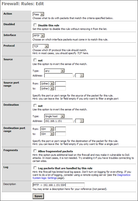
Save and Apply these rules as needed. Test them all to make sure they are working as designed. Most networks are compromised because no one checked the ACLs were activated or even working properly.
This is super easy, and you only have to type one piece of information the entire time!
Start by accessing the Network Connections Panel. (do this however you like, I prefer to right click “Network Places” and select Properties.)
Click “Create New Connection” in the left hand column of the “Network Connections” window.
You are now presented with a Wizard. Click Next to continue.
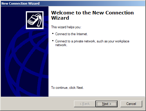
Select “Connect to the Network at my Workplace” from the menu.
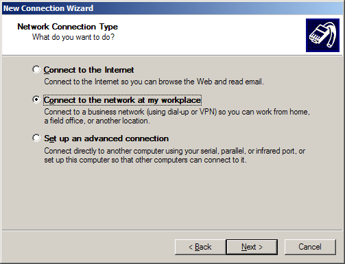
Select Virtual Private Network connection from the next panel.
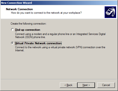
Name the connection.
Now enter the IP or FQDN of the PPTP Server. (This can be any of the configured interfaces.)
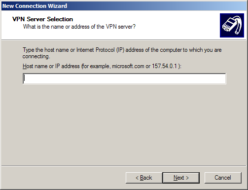
If you are the system admin you will be asked if you want this to be for your use only or for anyone’s use. I suggest you limit it to your use only unless you want the VPN network to be made available to all user accounts on the workstation.
Next you can either just finish or add a shortcut to the desktop. You are nearly done!
When you launch the client for the first time (hopefully from the icon you asked it to create from the wizard, if not then you will need to access the “Network Connections” window again and double click your new connection.) you will be asked for a username and password. Click connect when you are done with this and if all goes well you will connect to the PPTP Server.
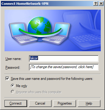
Start by opening a DOS window. (Command window)
Run ipconfig and you should get something similar to the next figure:
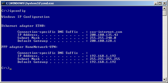
As you hopefully will see you have the settings for your physical adapter (in my case I renamed it to ETH0)
You will also see the PPP Adapter with the name you gave the VPN Connection when performing the steps in the last section. It should have an IP address that is in the range you defined for the PPTP Server. It should also have the subnet of 255.255.255.255 and it will be using itself as the default gateway. Just live with it; it is how it works.
For the more advanced who wish to know if things are all working right, Figure 6, displays a full ipconfig on the virtual adapter.

-
Now lets try doing something. If you followed the setup for this how-to you will have setup full access from the PPTP network to the LAN and WAN. If you setup selective rules you will have to test specifically what you setup. E.g. if you setup rules to only allow SMTP you will need to telnet to the host:25 that you designated in the firewall rule. Or write a new rule allowing ICMP to a host that will echo a reply back.
We will be sending a ICMP (Ping) to the firewall’s internal interface to test the VPN connection.
In my case the firewall is 192.168.1.1 (please use your internal address before writing to me to say pinging 192.168.1.1 didn’t work on your 10.x.x.x network. Hehe) If done right (assuming your firewall isn’t blocking internal ICMP packets) you are good for LAN access. (If you are blocking ICMP on the internal interface ping some other host on your home network.)
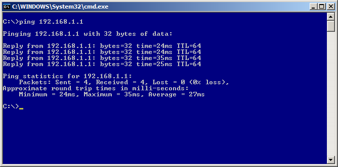
Now lets test beyond the firewall. Ping isn’t so good to use here as more and more people are blocking ICMP packets. So we will use tracert to check we are 1.) Routing via the PPTP tunnel and 2.) That we successful. Of course if you told the firewall to not allow WAN access then this step can be skipped.
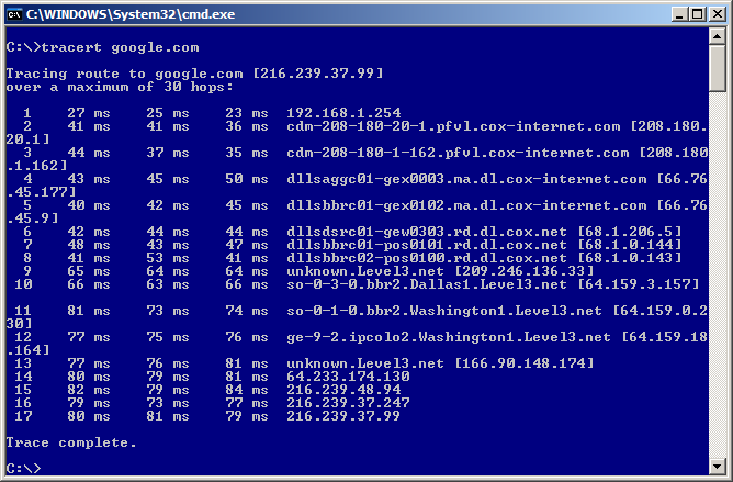
As seen in the last figure, the first hop is the PPTP “Server Address” as this is the gateway/interface for the PPTP Network.
Now check things like HTTP, etc. If you have this much and followed the directions you should be able to do everything.
These are more limits in PPTP than other VPN protocols.
NAT sometimes does not play nice with PPTP. Though m0n0wall seems to have this licked, and it works rather well.
Major “Gotcha!” If you are visiting a remote network where the network range is the same as the network range on the PPTP Network (your LAN network in most cases) then the PPTP tunnel will not work. E.g. You are using a WiFi connection in a local coffee shop and the network range it has put you in is 192.168.1.0/24. You try to connect to your home network via PPTP, but your home also uses 192.168.1.0/24. The tunnel/authentication to the PPTP server will happen, but no traffic will go across that tunnel due to the “confusion” in the TCP/IP stack on your workstation. To get around this use some odd network range at home. E.x. 192.168.88.0/24. Most people use 10.0.0.1 and 192.168.1.0 so try to set your home network differently. This will also help when you setup IPSEC tunnels between your house and say your friend’s house.
-
Some ISP's use unreasonably short DHCP lease times, like one hour. If the PPTP client machine gets a short lease from DHCP, it will lose internet connectivity after the lease expires. This is because all network traffic, including your DHCP renewal requests, are going across the VPN. Since it can't hit the local DHCP server through the VPN, when the lease expires your machine will release its IP address. This causes the loss of all connectivity. You have to disconnect from the PPTP (if it doesn't disconnect itself), renew your IP address, and reconnect. This is common on Windows hosts, and likely other OS's as well. If this happens, contact the administrator of your DHCP server (likely the client machine's ISP) and get the lease time lengthened.
The author has seen this situation numerous times, and in every case, the ISP was willing to help and resolved the problem. Your mileage may vary.
UPnP packets from your LAN do not make it to the PPTP network. This is more than likely because the current version of m0n0wall does not support UPnP. (In English: those of use having dreams of accessing our ReplayTV ™ or other media devices that use UPnP can dream of other things for now. It is actually more secure to not have UPnP on a firewall, but some people overlook that so they can use voice chat software and DVRs.)
Network Neighborhood in Windows does not work over PPTP connections because broadcasts are not forwarded across the PPTP connection.
I haven’t really beaten the PPTP tunnel that much yet, so if you find more items that don’t seem to work right let me know and I will add them here so people don’t go crazy trying to figure out something that just won’t work. ;)
OpenVPN was a temporary new addition to m0n0wall in the 1.2 beta versions. It was removed due to problems it caused with OPT interfaces, which have not been fixed to date and it is not available in any current m0n0wall release.
Table of Contents
Wireless functionality is available for selected wireless cards. The 1.2.x version of m0n0wall allows some 802.11b wireless adapters/chipsets (most notably Lucent Hermes and Intersil Prism II/2.5 to join a wireless network with WEP encryption. The upcoming 1.3.x version which is based on FreeBSD 6, supports (almost) all Atheros-based 802.11a/b/g cards as well (and some Ralink cards too) and offers more capabilities. Version 1.3.x allows the use of enhanced encryption, using the m0n0wall as an access point, and the capability to use a Radius server for authentication.
Note
Version 1.3.x m0n0wall is still in beta testing and features can change before it is released as a stable version.
Some of the m0n0wall wireless features include:
support for wi and ath wireless cards
support for 802.11b/g/a
channel selection from 1 to 14
support for hostap, BSS ad IBSS modes
enable/ disable wireless interface
SSID (hiding SSID in the upcoming 1.3 m0n0wall)
64bit or 128bit WEP encryption for ASCII or hexadecimal digits
Bridging with another Ethernet interface if using hostap mode
WPA and WPA2 encryption using PSK and Enterprise mode (in hostap mode of the upcoming 1.3 m0n0wall)
AES/CCMP and TKIP ciphers (in the upcoming 1.3 m0n0wall)
WPA Radius server parameters (in the upcoming 1.3 m0n0wall)
Note
A Wireless Distribution System (WDS) is currently not supported in either 1.2.x or 1.3.x.
The default m0n0wall configuration includes a LAN and WAN interface. If you have an installed wireless card you will have to add the interface manually. Below are the steps needed to install this interface using the web interface of your m0n0wall device.
log into the web interface of your m0n0wall device
click the + symbol at the bottom right of the Interface Assignment table
click on the drop down list and select a wireless interface (if no wireless cards are shown then either your wireless card is not correctly installed or it is not compatible with m0n0wall.
click the save button (your new wireless interface will appear under the Interfaces menu item of the web interface)
reboot your m0n0wall firewall for the changes to take effect
click the new wireless interface (probably named OPT1) and make your desired wireless configuration.
Below are the wireless parameters that are available in the m0n0wall firmware 1.2.x. They will be available only if you have a compatible wireless card installed and if you have added the wireless interface to your interface list.
Table 11.1. Wireless 1.2 Parameters
| Parameter | Description |
|---|---|
| Description | custom name for the interface |
| Bridge with | select an ethernet interface to bridge to the wirelss interface |
| IP address | assign the wireless interface an IP address and subnet mask |
| Standard | Select 802.11b/g/a |
| Mode | Note: To create an access-point, choose "hostap" mode. IBSS mode is sometimes also called "ad-hoc" mode; BSS mode is also known as "infrastructure" mode. |
| SSID | The service set identifier (SSID) is a 32 character name of your wireless network |
| Channel | Either choose Auto for the m0n0wall device to scan and find an available wireless channel or select a channel manually. To see currently used channels, click the Wireless option of the m0n0wall Status menu. |
| Station Name | Hint: this field can usually be left blank |
| Enable WEP | Check this box to enable WEP encryption of your wireless data |
| WEP Keys 1-4 | 40 (64) bit keys may be entered as 5 ASCII characters or 10 hex digits preceded by '0x'. 104 (128) bit keys may be entered as 13 ASCII characters or 26 hex digits preceded by '0x'. |
Below is a screenshot of the wireless interface configuration screen of 1.2.x m0n0wall.
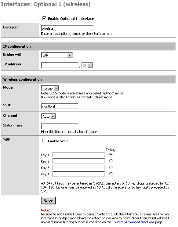
Below are the wireless parameters that are available in the upcoming m0n0wall firmware 1.3.x. They will be available only if you have a compatible wireless card installed and if you have added the wireless interface to your interface list.
Table 11.2. Wireless 1.3 Parameters
| Parameter | Description |
|---|---|
| Standard | Select 802.11b/g/a |
| Mode | Note: To create an access-point, choose "hostap" mode. IBSS mode is sometimes also called "ad-hoc" mode; BSS mode is also known as "infrastructure" mode. |
| SSID | The service set identifier (SSID) is a 32 character name of your wireless network |
| Hide SSID | If this option is selected, the SSID will not be broadcast in hostap mode, and only clients that know the exact SSID will be able to connect. Note that this option should never be used as a substitute for proper security/encryption settings. |
| Channel | Either choose Auto for the m0n0wall device to scan and find an available wireless channel or select a channel manually. To see currently used channels, click the Wireless option of the m0n0wall Status menu. |
| WPA Mode | Choose none to not use WPA encryption on your wireless data. Otherwise choose PSK to use a Preshared Key (password) or Enterprise to use a Radius server. |
| WPA Version | Choose from WPA, WPA2, or WPA+WPA2. In most cases, you should select "WPA + WPA2" here. |
| WPA Cipher | Choose from TKIP, AES/CCMP, or TKIP+AES/CCMP. AES/CCMP provides better security than TKIP, but TKIP is more compatible with older hardware. |
| WPA PSK | Enter the ASCII passphrase that will be used in WPA-PSK mode. This must be between 8 and 63 characters long. |
| Radius Server IP Address | Enter the IP address of the RADIUS server that will be used in WPA-Enterprise mode. |
| Radius Authentication Port | Leave this field blank to use the default port (1812). |
| Radius Accounting Port | Leave this field blank to use the default port (1813). |
| Radius Shared Secret | Optionally leave the shared secret blank to not use a RADIUS shared secret (not recommended). |
| Enable WEP | Check this box to enable WEP encryption of your wireless data |
| WEP Keys 1-4 | 40 (64) bit keys may be entered as 5 ASCII characters or 10 hex digits preceded by '0x'. 104 (128) bit keys may be entered as 13 ASCII characters or 26 hex digits preceded by '0x'. |
Below is a screenshot of the wireless interface configuration screen of 1.3.x m0n0wall.
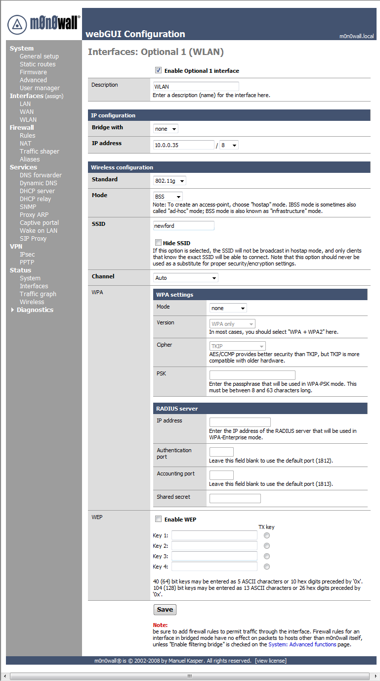
Table of Contents
This Captive Portal functionality allows you to control HTTP browser access to the Internet. All users trying to leave the selected network (for example all users from the LAN network going to the Internet) will be redirected to a HTML page stored on your m0n0wall. This page is typically where the user trying to reach the Internet can enter in username and password information to be authenticated and allowed access to the Internet.
Users are identified by their MAC hardware address of their ethernet card. All traffic trying to reach the Internet or selected network by any user is blocked until they use a web browser and finish the authentication process on the HTML authentication page.
Some features of the m0n0wall Captive Portal include:
Interface selection (typically the LAN interface)
Allow selected IP or MAC addresses
User authentication choices (none, local, or RADIUS)
Maximum concurrent connections
Concurrent user logins
Local user management option
Per user bandwidth restrictions
Idle and Hard timeout
Log out popup window
Redirection URL
MAC filtering
HTTPS authentication
Customizable portal page contents
Customizable authentication failure page
Voucher support (in the upcoming 1.3 m0n0wall)
Caution
Don't forget to enable the DHCP server on your captive portal interface! Make sure that the default/maximum DHCP lease time is higher than the timeout entered on this page. Also, the DNS forwarder needs to be enabled for DNS lookups by unauthenticated clients to work.
Below are some of the Connection options that can be configured for use with the Captive Portal. Additionally there is some information about allowing pass-through MAC addresses and making a list of allowed IP addresses that do not need authentication.
Table 12.1. Connection Parameters
| Parameter | Description |
|---|---|
| Interface | Choose which interface to run the captive portal on. Captive Portal can only be run on one interface. |
| Maximum concurrent connections | This setting limits the number of concurrent connections to the captive portal HTTP(S) server. This does not set how many users can be logged in to the captive portal, but rather how many users can load the portal page or authenticate at the same time! Default is 4 connections per client IP address, with a total maximum of 16 connections. |
| Idle timeout | Clients will be disconnected after this amount of inactivity. They may log in again immediately, though. Leave this field blank for no idle timeout. |
| Hard timeout | Clients will be disconnected after this amount of time, regardless of activity. They may log in again immediately, though. Leave this field blank for no hard timeout (not recommended unless an idle timeout is set). |
| Logout popup window | If enabled, a popup window will appear when clients are allowed through the captive portal. This allows clients to explicitly disconnect themselves before the idle or hard timeout occurs. |
| Redirection URL | If you provide a URL here, clients will be redirected to that URL instead of the one they initially tried to access after they've authenticated. |
| Concurrent user logins | If this option is set, only the most recent login per username will be active. Subsequent logins will cause machines previously logged in with the same username to be disconnected. |
| MAC filtering | If this option is set, no attempts will be made to ensure that the MAC address of clients stays the same while they're logged in. This is required when the MAC address of the client cannot be determined (usually because there are routers between m0n0wall and the clients). |
| Per-user bandwidth restriction | If this option is set, the captive portal will restrict each user who logs in to the specified default bandwidth. RADIUS can override the default settings. Leave empty or set to 0 for no limit. You will need to enable the traffic shaper for this to be effective. |
Adding MAC addresses as pass-through MACs allows them access through the captive portal automatically without being taken to the portal page. The pass-through MACs can change their IP addresses on the fly and upon the next access, the pass-through tables are changed accordingly. Pass-through MACs will however still be disconnected after the captive portal timeout period.
You can enter a list of MAC address (6 hex octets separated by colons) and a description here for your reference (it is not parsed).
Adding allowed IP addresses will allow IP access to/from these addresses through the captive portal without being taken to the portal page. This can be used for a web server serving images for the portal page or a DNS server on another network, for example. By specifying from addresses, it may be used to always allow pass-through access from a client behind the captive portal.
Some sample rules are:
any x.x.x.x > All connections to the IP address are allowed
x.x.x.x > any All connections from the IP address are allowed
For each entry on the Allowed IP Address list you can use From to always allow an IP address through the captive portal (without authentication). Use To to allow access from all clients (even non-authenticated ones) behind the portal to this IP address. Additionally each entry will contain an IP address and a description for your reference (it is not parsed).
Caution
If you have servers such as web or email on a separate subnetwork (for example a DMZ) be sure to add their IP addresses to this list. Otherwise users will not be allowed to access them without authenticating first.
There are 3 user management choices that can be used to authenticate users to the Captive Portal.
No authentication
Local user manager
Radius authentication
Optionally web authentication can be secured with HTTPS.
Below are some of the Secure Authentication options that can be configured for use with th Captive Portal to .
Table 12.2. Secure Authentication Parameters
| Parameter | Description |
|---|---|
| HTTPS login | If enabled, the username and password will be transmitted over an HTTPS connection to protect against eavesdroppers. A server name, certificate and matching private key must also be specified below. |
| HTTPS server name | This name will be used in the form action for the HTTPS POST and should match the Common Name (CN) in your certificate (otherwise, the client browser will most likely display a security warning). Make sure captive portal clients can resolve this name in DNS. |
| HTTPS certificate | Paste a signed certificate in X.509 PEM format here. |
| HTTPS private key | Paste an RSA private key in PEM format here. |
When using the Local User Manager option for Authentication it is possible to store and access a list of users on the m0n0wall device itself. This list is manually entered from the web interface and includes the following parameters.
Table 12.3. User Parameters
| Parameter | Description |
|---|---|
| Username | The name a user will use to authenticate with |
| Password | The password a user will use to authenticate with |
| Fullname | User's full name, for your own information only |
| Expiration Date | Leave blank if the account shouldn't expire, otherwise enter the expiration date in the following format: mm/dd/yyyy |
When using the Radius Authentication option for Authentication it is possible to authenticate with an existing Radius server on a connected network. The Radius server will manage the user authentication requests. This list is manually entered from the web interface and includes the following parameters.
Table 12.4. Radius Server Parameters
| Parameter | Description |
|---|---|
| Primary RADIUS server | Enter the IP address of the RADIUS server which users of the captive portal have to authenticate against. You can change the default port (1812) and shared secret. Optionally leave the shared secret blank to not use a RADIUS shared secret (not recommended). |
| Secondary RADIUS server | If you have a second RADIUS server, you can activate it by entering its IP address, port and shared secret as done for the primary server. |
| send RADIUS accounting packets | If this is enabled, RADIUS accounting packets will be sent to the primary RADIUS server. Optionally change the default port (1813). |
| Reauthentication | If reauthentication is enabled, Access-Requests will be sent to the RADIUS server for each user that is logged in every minute. If an Access-Reject is received for a user, that user is disconnected from the captive portal immediately. |
| Accounting updates | These reauthentication updates can be configured to support no accounting updates, stop/start accounting, or interim updates. |
| RADIUS MAC authentication | If this option is enabled, the captive portal will try to authenticate users by sending their MAC address as the username and a static password/secret to the RADIUS server. |
| RADIUS Session-Timeout attributes | When this is enabled, clients will be disconnected after the amount of time retrieved from the RADIUS Session-Timeout attribute. |
| Radius Type | If RADIUS type is set to Cisco, in RADIUS requests (Authentication/Accounting) the value of Calling-Station-Id will be set to the client's IP address and the Called-Station-Id to the client's MAC address. Default behaviour is Calling-Station-Id = client's MAC address and Called-Station-Id = m0n0wall's WAN MAC address. |
| MAC address format | This option changes the MAC address format used in the whole RADIUS system. Change this if you also need to change the username format for RADIUS MAC authentication. default: 00:11:22:33:44:55 singledash: 001122-334455 ietf: 00-11-22-33-44-55 cisco: 0011.2233.4455 unformatted: 001122334455 |
It is possible to customize the HTML pages that are used for the Captive portal authentication process. The page that does the authentication itself an be changed as well as the default page that is shown for a failed authentication. Graphics files can also be loaded into the m0n0wall device for use on these pages, up to a maximum of 256 KB.
Optionally a redirected URL can be used where clients will be redirected instead of the one they initially tried to access after they've authenticated. After reading this information they are free to access the remote networks since they have already been authenticated.
Below are the parameters for custom pages and files.
Upload an HTML file for the portal page here (leave blank to keep the current one). Make sure to include a form (POST to "$PORTAL_ACTION$") with a submit button (name="accept") and a hidden field with name="redirurl" and value="$PORTAL_REDIRURL$". Include the "auth_user" and "auth_pass" input fields if authentication is enabled, otherwise it will always fail. Example code for the form:
<form method="post" action="$PORTAL_ACTION$">
   <input name="auth_user" type="text">
   <input name="auth_pass" type="password">
   <input name="redirurl" type="hidden" value="$PORTAL_REDIRURL$">
   <input name="accept" type="submit" value="Continue">
</form>
The contents of the HTML file that you upload here are displayed when an authentication error occurs. You may include "$PORTAL_MESSAGE$", which will be replaced by the error or reply messages from the RADIUS server, if any. You may also include a new login form in the error page to allow the user to attempt another login directly.
The loading page for custom files can be found in the File Manager section of the Captive Portal main menu.
Any files that you upload here will be made available in the root directory of the captive portal HTTP(S) server. You may reference them directly from your portal page HTML code using relative paths. Example: you've uploaded an image with the name 'test.jpg' using the file manager. Then you can include it in your portal page like this:
<img src="test.jpg" width=... height=...>
The total size limit for all files is 256 KB.
Below is a quick howto from mwiget who added the Voucher feature to m0n0wall. Vouchers are only available in the upcoming 1.3 firmwar release and are currently part of the beta version of the firmware.
Below are the steps to quickly setup and use the voucher functionality of m0n0wall's Captive Portal.
To enable, create and manage voucher support via captive portal, there is a new Tab under Services->Captive Portal: Voucher.
Enable captive portal first, upload a landing page that contains an input field 'auth_voucher'. An example can be found on the the URL above.
Then enable Voucher support on the Voucher tab. Initially you can leave all fields with its defaults. Every new install will create unique encryption keys.
Now add at least one "Roll" by clicking '+' on the Vouchers page, right to 'Voucher rolls': Specify a Roll Number, e.g. 0, how many vouchers that roll shall contain, and how long each voucher allows network access.
Then generate the new vouchers by clicking on the paper logo right to the newly added roll. This will generate a CSV file and download via your browser.
Each of these generated vouchers can now be used by users for the configured amount of minutes for that roll. Note that as soon as a voucher has been activated, its timer will run down to zero and then block access, no matter if the session is idle or got disconnected due to logout or session termination.
To test the vouchers in the m0n0wall GUI, click on Status->Captive Portal. New tabs, dedicated to voucher handling, show up when voucher support is enabled. Click on status->captive portal-> Test Vouchers and enter one or more of the newly generated vouchers from the downloaded CSV file and click submit. A message will be shown with the validation and duration of each given voucher.
One can add multiple rolls, e.g. to have vouchers with different time credit. It is also possible, to enter multiple vouchers, separated by space, to gain the sum of time credit of all entered vouchers.
There is more to it, read the comments to each config parameter on the voucher page.
Note on the very short public/private RSA keys: I know, those can be cracked easy and in no time, if one of the keys is known. The idea here was to make it a little bit harder than simply adding a shared password into the m0n0wall config file. Unfortunately I'm no expert on encryption but I assume with such short encrypted vouchers, there is no security difference between the used RSA keys and a symmetric encryption. Anyhow, all that encryption/decryption stuff is done in a newly added binary C program voucher.c, that is compiled and added into the m0n0wall image, and can be modified to increase the usability and security.
Below are the following parameters that can be configured for voucher use in the upcoming 1.3 m0n0wall). The Enable Vouchers checkbox must activated for these parameters to be used.
Note
Changing any Voucher parameter (apart from managing the list of Rolls) on this page will render existing vouchers useless if they were generated with different settings.
Table 12.5. Voucher Parameters
| Parameter | Description |
|---|---|
| Voucher Rolls | Create, generate and activate Rolls with Vouchers that allow access through the captive portal for the configured time. Once a voucher is activated, its clock is started and runs uninterrupted until it expires. During that time, the voucher can be re-used from the same or a different computer. If the voucher is used again from another computer, the previous session is stopped. |
| Voucher public key | Paste an RSA public key (64 Bit or smaller) in PEM format here. This key is used to decrypt vouchers. |
| Voucher private key | Paste an RSA private key (64 Bit or smaller) in PEM format here. This key is only used to generate encrypted vouchers and doesn't need to be available if the vouchers have been generated offline. |
| Character set | Tickets are generated with the specified character set. It should contain printable characters (numbers, lower case and upper case letters) that are hard to confuse with others. Avoid e.g. 0/O and l/1. |
| # of Roll Bits | Reserves a range in each voucher to store the Roll# it belongs to. Allowed range: 1..31. Sum of Roll+Ticket+Checksum bits must be one Bit less than the RSA key size. |
| # of Ticket Bits | Reserves a range in each voucher to store the Ticket# it belongs to. Allowed range: 1..16. Using 16 bits allows a roll to have up to 65535 vouchers. A bit array, stored in RAM and in the config, is used to mark if a voucher has been used. A bit array for 65535 vouchers requires 8 KB of storage. |
| # of Checksum Bits | Reserves a range in each voucher to store a simple checksum over Roll# and Ticket#. Allowed range is 0..31. |
| Magic Number | Magic number stored in every voucher. Verified during voucher check. Size depends on how many bits are left by Roll+Ticket+Checksum bits. If all bits are used, no magic number will be used and checked. |
| Save Interval | The list of active and used vouchers can be stored in the system's configuration file once every x minutes to survive power outages. No save is done if no new vouchers have been activated. Enter 0 to never write runtime state to XML config. |
| Invalid Voucher Message | Error message displayed for invalid vouchers on captive portal error page ($PORTAL_MESSAGE$) |
| Expired Voucher Message | Error message displayed for expired vouchers on captive portal error page ($PORTAL_MESSAGE$). |
Each voucher roll has the following parameters.
Table 12.6. Voucher Roll Parameters
| Parameter | Description |
|---|---|
| Roll# | Enter the Roll# (0..65535) found on top of the generated/printed vouchers. |
| Minutes per Ticket | Defines the time in minutes that a user is allowed access. The clock starts ticking the first time a voucher is used for authentication. |
| Count | Enter the number of vouchers (1..1023) found on top of the generated/printed vouchers. WARNING: Changing this number for an existing Roll will mark all vouchers as unused again. |
| Comment | Can be used to further identify this roll. Ignored by the system. |
Because users are identified by their MAC hardware address it is possible that someone using a packet sniffer can spoof/ impersonate the authenticated MAC hardware address and thereby gain network access. Setting a hard timeout can help to minimize this risk.
Don't forget to enable the DHCP server on your captive portal interface! Make sure that the default/maximum DHCP lease time is higher than the timeout entered on this page. Also, the DNS forwarder needs to be enabled for DNS lookups by unauthenticated clients to work.
Plan carefully when you will make changes to the Captive Portal configuration. Changing any settings on the main Captive Portal configuration window will disconnect all clients!
Because of the way Captive Portal is implemented, it cannot be used on more than one interface.
Chris Burrows contributed A duffers guide to setting up a portal to allow visitors limited access to the Internet.
Jonathan De Graeve has implemented a number of new RADIUS features for Captive Portal that will be implemented in a future beta version. For now, these features are available on test images available for download from http://inf.imelda.be/downloads/m0n0wall/.
Features currently implemented in the test images include:
RADIUS-defined URL redirection taking precedence over URL redirection parameter in captive portal setup page.
Multiple RADIUS server support
Failure message on captive portal login error page, plus logging to the captive portal log on why authentication failed (user account exceeded bandwidth limit, bad password, etc.).
Cisco-compatible feature (sending calling-station-id with clientip and called-station-id with clientmac instead of standard behavior calling-station-id and clientmac).
Timeout parameter and max authentication retries parameter
retrieval of user bandwidth settings
retrieval of user group
retrieval of session-timeout
Note
Retrieval means the variable is present and CAN be used, but there is no action bound to it yet.
You can utilize Captive Portal and its MAC pass-through functionality for rudimentary MAC address restrictions.
Enable Captive Portal on the desired interface (e.g. LAN) at the Services -> Captive Portal screen. Create a HTML page of your liking that does not include the submit button so the user cannot authenticate with the captive portal. Other settings can all be left at their defaults.
Click the "Pass-through MAC" tab on the Captive Portal screen. Click the + to start adding permitted MAC addresses. In the MAC address box, type in the six hex octets separated by colons (e.g. ab:cd:ef:12:34:56), optionally (but recommended) enter a description, and click Save. Repeat for every authorized host on your network.
Table of Contents
This section will explain how to add a DMZ interface to the two interface (LAN/WAN) base configuration from the Quick Start Guide.
You must have a functioning two interface setup before starting on configuring your DMZ interface.
The 1:1 NAT DMZ setup is most appropriate where you have multiple public IP's and wish to assign a single public IP to each DMZ host.
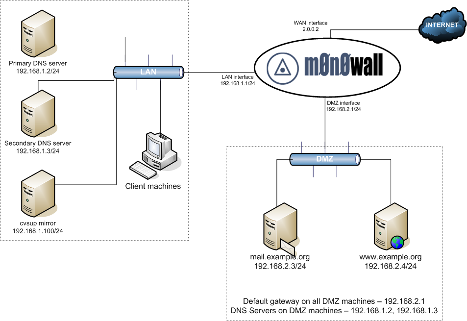
This depicts the network layout we will have after configuring our DMZ interface.
Log into your m0n0wall's webGUI, and click "(assign)" next to Interfaces.
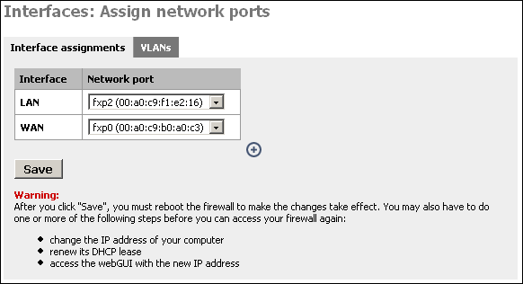
Click the ![]() on this page to add your third interface.
on this page to add your third interface.
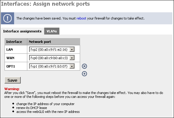
Now restart your m0n0wall for the changes to take affect.
After your m0n0wall restarts, log back into the webGUI. Under Interfaces, you will see OPT1. Click on it.

Check the box at the top to enable the interface, give it a more descriptive name (I'll call it "DMZ"), and set up the desired IP configuration. The IP subnet must be different from the LAN subnet.
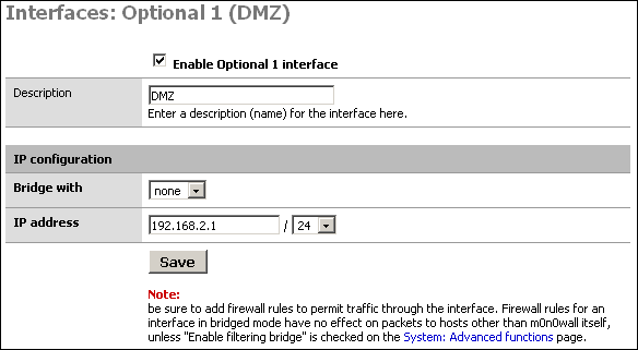
The main purpose of a DMZ is to protect the LAN from the publicly-accessible Internet hosts on your network. This way if one of them were to be compromised, your LAN still has protection from the attacker. So if we don't block traffic from the DMZ to the LAN, the DMZ is basically useless.
First we will put in a firewall rule on the DMZ interface denying
all traffic to the LAN while still permitting all traffic to the WAN.
Click Firewall -> Rules, and click the ![]() at the bottom of the page.
at the bottom of the page.
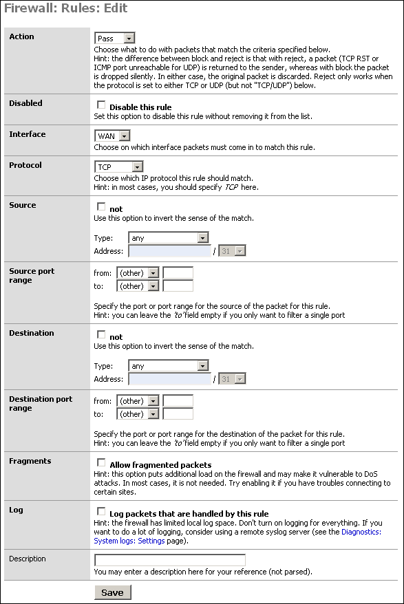
Filling out this screen as shown below will permit all traffic out the DMZ interface to the internet, but prohibit all DMZ traffic from entering the LAN. It also only permits outbound traffic from the DMZ's IP subnet since only traffic from a source IP within your DMZ should come in on the DMZ interface (unless you have a routed DMZ, which would be strange). This prevents spoofed packets from leaving your DMZ.
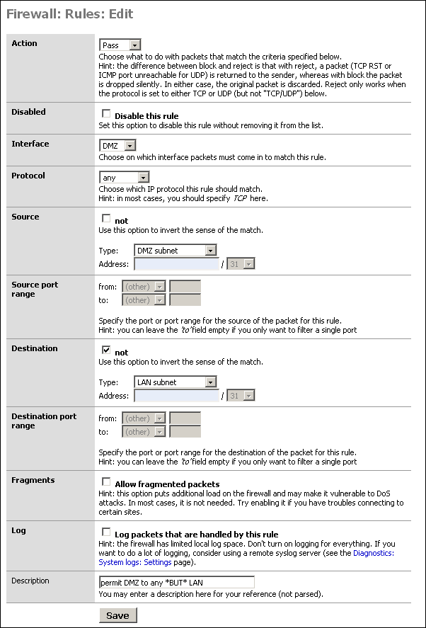
Click Save after verifying your selections. Then click Apply Changes.
You probably have some services on your LAN that your DMZ hosts will need to access. In our sample network, we need to be able to reach DNS on the two LAN DNS servers, cvsup protocol to our LAN cvsup-mirror server, and NTP for time synchronization to the time server that resides on the cvsup-mirror server.
Always use specific protocols, ports, and hosts when permitting traffic from your DMZ to your LAN. Make sure nothing that isn't required can get through.
Note
Don't forget that source ports (TCP and UDP) are randomly selected high ports, and not the same as the destination port. You'll need to use "any" for source port.
My DMZ interface firewall rules now look like the following after permitting the required services from DMZ to LAN.
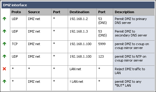
Note that I added a rule to deny any traffic coming in on the DMZ interface destined for the LAN. This was not required because of the way we configured the allow rule, however I like to put it in there to make it very clear where the traffic from DMZ to LAN is getting dropped.
When entering your rules, remember they are processed in top down order, and rule processing stops at the first match. So if you had left the rule we added above as the top rule, it would drop packets from DMZ to LAN without getting to the permit rules you added. I recommend you design your rules similar to how I have, with drop DMZ to LAN as the second last line, and permit DMZ to any except LAN as the last line.
Now you need to determine whether you'll use inbound or 1:1 NAT. If you have multiple public IP's, use 1:1 NAT. If you have only a single public IP, you'll need to use inbound NAT. If you have multiple public IP's, but more DMZ hosts than public IP's, you can use inbound NAT, or a combination of 1:1 and inbound.
For this scenario, we'll say we have a /27 public IP subnet. We'll say it's 2.0.0.0/27. m0n0wall's WAN interface has been assigned with IP 2.0.0.2. I will use 1:1 NAT to assign the public IP 2.0.0.3 to the DMZ mail server and 2.0.0.4 to the DMZ web server.
Go to the Firewall -> NAT screen and click the 1:1 tab. Click
the ![]() . I will add two entries, one each for the mail
server and web server.
. I will add two entries, one each for the mail
server and web server.
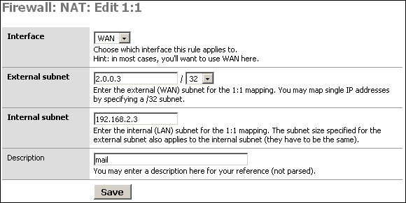
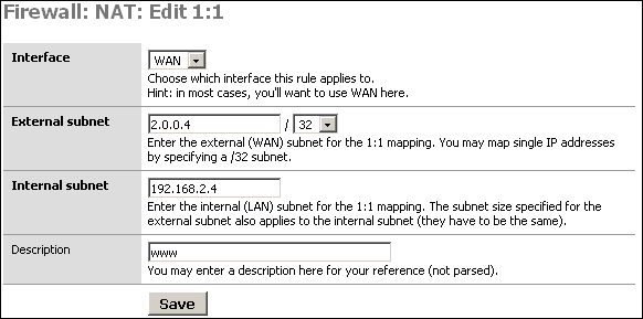
After adding the rules, click Apply changes. You'll now see something like the following.
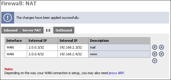
You can test the 1:1 NAT we just configured by going to whatismyip.com on the machine configured for 1:1. If you don't have a GUI, lynx will work, or you can fetch or wget the URL and cat the resulting file. (fetch http://whatismyip.com && cat whatismyip.com | grep "IP is").
You should see the IP is the one you just configured in 1:1 NAT. If you get an IP other than the one you configured in 1:1, there is a problem with your configuration.
If you have only one public IP, or more need more
publicly-accessible servers than you have public IP addresses, you'll
need to use inbound NAT. Go to the NAT screen, and on the Inbound tab,
click ![]() .
.
For this example, we will assume you have only one public IP, and it is the interface address of the WAN interface.
First, anything to the WAN IP to port 25 (SMTP) will go to the mail server in our DMZ.
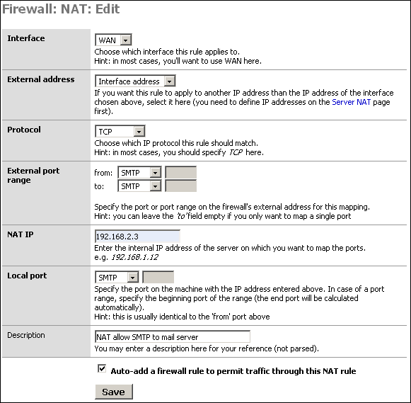
Click Save, and click ![]() to add the inbound NAT rule for the HTTP
server.
to add the inbound NAT rule for the HTTP
server.
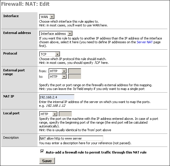
Click "Apply changes" and your configuration will be working. It should look like the following.
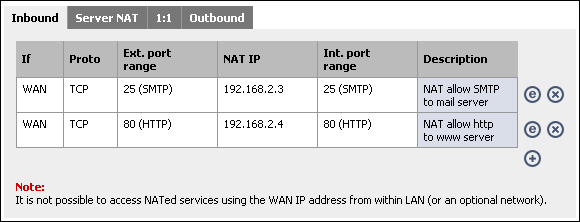
We've limited DMZ hosts' accessibility to the LAN, but we can lock it down a step further using egress filtering. Many DMZ hosts don't need to be able to talk out to the Internet at all, or possibly only while you are running updates or doing maintenance or need to download software.
If we can keep our DMZ hosts from accessing the Internet, we can make an attacker's job much more difficult. Many exploits rely on the target being able to pull files from a machine the attacker controls, or in the case of a worm, from the infected host. I'll use Code Red and Nimda as an example. Infected hosts exploited the vulnerability, and the remote host pulled the infected admin.dll via TFTP from the already infected host. If you were running vulnerable web servers, but did not allow TFTP traffic outbound from your webservers, you could not have been infected. (reference)
Attackers most always try to pull in a tool kit or root kit of some sort onto machines they exploit. There are ways around this, but it just makes it that much more difficult. This will merely slow down a knowledgeable attacker (who'll find a way to get in one way or another), but it could stop a script kiddie dead in their tracks and keep some worms from infecting your network.
This is not a replacement for proper patching and other security measures, it's just good practice in a defense-in-depth strategy.
How does this work?
You might be wondering how your servers will be able to serve content while not being able to talk out to the Internet. I'll use web servers as an example. When packets come in on the WAN interface through firewall rules you have entered to permit HTTP traffic, there is a state entry that permits any return traffic from that connection to traverse the firewall.
Remember this only affects the ability to initiate connections outbound, not the ability to respond to incoming traffic requests.
Recommended configuration
As with all firewall rules, limit the accessibility as much as possible. Mail servers that must send outbound mail will need to initiate connections to destination TCP port 25 to any host. If the DNS servers your DMZ hosts use reside outside of the DMZ, you'll need to allow UDP port 53 to the DNS servers being used.
I typically put in rules for upgrade purposes to permit outbound traffic to the ports required. For FreeBSD, TCP 5999 (cvsup) and TCP 80 (HTTP) will generally suffice. When I'm not upgrading the system, I use the "disable" checkbox to disable the rule, but leave it in place to easily enable it when needed. Just always remember to disable it when you're done updating the system.
A filtered bridge is a common way of configuring a DMZ segment. This can be used as a typical DMZ where you have hosts on the LAN interface, but is probably more frequently used to protect servers at a colocation facility where there are no LAN hosts.
Note
Remember you cannot access hosts on a bridged interface from a NAT'ed interface, so if you do have a LAN interface set up, you won't be able to access the hosts on the bridged interface from the LAN.
Network Diagram for this Configuration
The following diagram depicts the example configuration described in this section. The colocation facility has assigned you with the subnet 111.111.111.8/29, which includes usable IP's .9-.14. One of those is required for the colo's router, so you end up with 5 usable IP's.
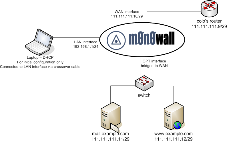
After you have your network set up as shown, and the interfaces and LAN IP assigned appropriately, log into the webGUI to begin the initial configuration.
First go to System -> General setup, and configure the hostname, domain, DNS servers, change the password, switch the webGUI to HTTPS, and set your time zone. Click Save, and reboot m0n0wall for the changes to take affect.
Log back into the webGUI and go to the Interfaces -> WAN page. For the example network, we'll assign the static IP 111.111.111.10/29, default gateway 111.111.111.9. Unless your WAN network is private IP's, check the "Block private networks" box. Click Save.
Click Interfaces -> OPT. Name the interface to your liking (for the example, we'll use Servers for the name). In the "Bridge with" box, select WAN. Click Save.
Go to the System -> Advanced page and check the "Enable filtering bridge" box. Click Save.
Go to the Firewall -> Rules screen.
Note
Chances are for any configuration, especially if you're restricting outbound connections, you'll need a much more involved ruleset than is depicted here. Open what you know you need open, and watch for dropped traffic in your logs to see what else you might need to open. It takes some effort to get your firewall locked down as tightly as it can possibly be, but the long term effect of increased security is well worth the time spent.
Initially, you may want to configure a rule on the OPT interface permitting traffic to anywhere, then after things are working, tightening that rules as desired. For this example, we'll go ahead and implement locked down rules from the get go.
The mail server on our bridged interface needs to send mail to any host on the Internet. Both servers need to get to DNS servers at 111.111.110.2 and 111.111.109.2. We'll add disabled maintenance rules for HTTP and cvsup.
Since this example portrays a firewall at a colocation facility, we need a remote administration rule to allow traffic from our trusted location's static IP access to administration functions of the servers, as well as the m0n0wall webGUI. For this example, we'll permit all traffic from the trusted location (IP 11.12.13.30). You may want to tighten this rule. If you don't have anything on the LAN segment, remember to allow remote administration from somewhere so you can get into the webGUI without being on site.
We also need to add rules to permit SMTP traffic to the mail server and HTTP and HTTPS traffic to the web server.
You can leave or remove the default LAN to any rule if you don't have hosts on the LAN interface. In the example, the LAN interface will be unplugged once the onsite configuration is completed.
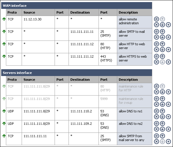
Table of Contents
m0n0wall can connect to any third party VPN device that supports standard IPsec site to site VPN's, which includes most any VPN device and firewall with IPsec VPN support.
This chapter will provide instructions on connecting m0n0wall with a number of third party IPsec devices.
Have you configured a VPN between m0n0wall and a device not listed here? Please document how you accomplished this. There is a section of the wiki dedicated to configurations for this chapter.
Below you will find sample configurations for the following devices.
Cisco PIX Firewall
Smoothwall
FreeS/WAN
Sonicwall
Nortel
The following describes how to configure a site to site IPsec VPN tunnel between a PIX Firewall and m0n0wall.
First we need to make sure the PIX has 3DES enabled.
pixfirewall# sh ver

Cisco PIX Firewall Version 6.3(3)
Cisco PIX Device Manager Version 2.0(2)

Compiled on Wed 13-Aug-03 13:55 by morlee

pixfirewall up 157 days 5 hours

Hardware: PIX-515E, 32 MB RAM, CPU Pentium II 433 MHz
Flash E28F128J3 @ 0x300, 16MB
BIOS Flash AM29F400B @ 0xfffd8000, 32KB

0: ethernet0: address is 000b.4605.d319, irq 10
1: ethernet1: address is 000b.4605.d31a, irq 11
2: ethernet2: address is 0002.b3b3.2e54, irq 11
Licensed Features:
Failover: Disabled
VPN-DES: Enabled
VPN-3DES-AES: Enabled
If the "VPN-3DES-AES" line above does not show "Enabled", you need to install the PIX 3DES key. This is now available free from Cisco here for all PIX firewalls (click 3DES/AES Encryption License). Do NOT use DES for a VPN if you want it to be cryptographically secure. DES is only slightly better than transmitting in clear text.
Next we'll see if any VPN configurations are in place on the PIX.
pixfirewall# sh isakmp policy

Default protection suite
encryption algorithm: DES - Data Encryption Standard (56 bit keys).
hash algorithm: Secure Hash Standard
authentication method: Rivest-Shamir-Adleman Signature
Diffie-Hellman group: #1 (768 bit)
lifetime: 86400 seconds, no volume limit
If you only see the default policy, there are no VPN's configured. This document cannot be followed verbatim if you have current VPN's (though you should be able to figure it out, just be careful not to break your existing VPN's with any duplicate names).
Allow IPSec connections to the PIX
pixfirewall(config)# sysopt connection permit-ipsec
Enable ISAKMP on the outside interface (where "outside" is the name of the internet-facing interface)
pixfirewall(config)# isakmp enable outside
isakmp policy command on PIX
pixfirewall(config)# isakmp policy ?
Usage: isakmp policy %lt;priority> authen %lt;pre-share|rsa-sig>
isakmp policy %lt;priority> encrypt %lt;aes|aes-192|aes-256|des|3des>
isakmp policy %lt;priority> hash %lt;md5|sha>
isakmp policy %lt;priority> group %lt;1|2|5>
isakmp policy %lt;priority> lifetime %lt;seconds>
Now we need to configure the ISAKMP policy on the PIX. Enter the following commands in configure mode:
isakmp policy 10 authen pre-share
isakmp policy 10 encrypt 3des
isakmp policy 10 hash md5
isakmp policy 10 group 2
isakmp policy 10 lifetime 86400
This policy uses pre-shared keys as authenticator, 3DES encryption, md5 hashing, group 2, and 86400 second lifetime.
Now we need to define the pre-shared key for this connection. (1.1.1.1 = public IP address of m0n0wall, qwertyuiop is the shared key, randomly generate something to use for your configuration)
isakmp key qwertyuiop address 1.1.1.1 netmask 255.255.255.255
Now we need to create an access list defining what traffic can cross this tunnel.
access-list monovpn permit ip 10.0.0.0 255.255.255.0 10.0.1.0 255.255.255.0
access-list monovpn permit ip 10.0.0.0 255.255.255.0 10.0.1.0 255.255.255.0
Define transform set for this connection called "monovpnset"
crypto ipsec transform-set monovpnset esp-3des esp-md5-hmac
Define security association lifetime
crypto ipsec security-association lifetime seconds 86400 kilobytes 50000
Now to set up the actual connection, the crypto map "monovpnmap". (where 1.1.1.1 is the public IP address of the m0n0wall device)
crypto map monovpnmap 10 ipsec-isakmp
crypto map monovpnmap 10 set peer 1.1.1.1
crypto map monovpnmap 10 set transform-set monovpnset
crypto map monovpnmap 10 match address monovpn
These lines specify type of VPN (ipsec-isakmp), peer IP address (1.1.1.1), transform set to be used (monovpnset, defined above), and that packets matching the access list "monovpn" created above should traverse this VPN connection.
Last step is to tell the PIX to not use NAT on the packets using this VPN connection and route them instead.
First we'll see if anything is currently routed.
pixfirewall# sh nat
nat (inside) 0 access-list no-nat
Look for "nat (interface) 0 ..." commands. The above means any traffic matching access list "no-nat" will routed, not translated. In this instance, we are adding to a current access list (if you use a DMZ, you likely have something similar to this set up).
access-list no-nat permit ip 10.0.0.1 255.255.255.0 10.0.1.0 255.255.255.0
access-list no-nat permit ip 10.0.1.0 255.255.255.0 10.0.0.0 255.255.255.0
If you do not have a "nat (interface) 0 ..." command in your "sh nat" output, you can use the above two lines to create a "no-nat" access list. You then have to apply it with the "nat (interface-name) 0 access-list no-nat" command (replacing "interface-name" with the name of your LAN interface).
Log into the m0n0wall web GUI, and under VPN, click IPSec.
If the "Enable IPSec" box is not checked, check it and click Save.
Click the + button to add a VPN tunnel. On the "Edit tunnel" screen, fill in as follows:
Leave "Disable this tunnel" box unchecked.
Interface "WAN"
Local subnet: Type: "LAN subnet"
Remote subnet: 10.0.0.0 /24 (fill in the subnet of the network behind the PIX here, rather than the made-up 10.0.0.0/24)
Remote gateway: public IP address of PIX
Description: add one to describe the connection (e.g. "PIX VPN")
Phase 1
Negotiation mode: Aggressive
My identifier: "My IP Address"
Encryption algorithm: 3DES
Hash algorithm: MD5
DH key group: 2
Lifetime: 86400
Pre-shared key: qwertyuiop (enter exactly what you defined as your pre-shared key on the PIX earlier)
Phase 2
Protocol: ESP
Encryption algorithms: only 3DES checked
Hash algorithms: only MD5 checked
PFS key group: 2
Lifetime: 86400
Note
In m0n0wall 1.2 beta versions, you may experience the connection dropping frequently with this configuration. If this happens, set the PFS key group in phase 2 to "off".
Note
If you don't specify a key lifetime in the m0n0wall config, the tunnel will work, but appear to go insane after a while. Supposedly Cisco's will negotiate a key lifetime, but I have not seen this work in my experience. This is also true of a Cisco VPN Concentrator. (anonymous wiki contribution)
Rev. Tig posted the following information on connecting Smoothwall and m0n0wall via IPsec VPN in a post on the mailing list on September 30, 2004.
I could not find a working solution in the mailing list archives but
here is how I have managed to create a VPN between Smoothwall Corporate
with Smoothtunnel and m0n0wall and I thought I would share it here to
same people going through the same headbashing experience I did :) This
will be far to much of a teaching granny to suck eggs for most people on
the list but it might help someone get up and running quickly.

Variety is the spice of life and just to confuse matters the m0n0wall
box was stuck behind NAT :) The office I was linking to was in a
serviced building and hence the connection was a shared one with a
private IP and public one port forwarded to it.

I had never done this before so corrections are welcome :) I am not
saying these are the best settings all I know is my VPN is up and
running and it seems to be happy :)

What I have created is a VPN between one subnet at one site running
Smoothwall Corporate Server 3.0 with Smoothtunnel and a m0n0wall v1
box sitting behind NAT with a private IP at the other site. Any other
versions of the software may need slightly different settings but
hopefully this should put you in the right ballpark.

First off IPSEC over NAT, if at all possible don't :) If you have to
or for some perverse reason you fancy a crack at this then read on, if
you are just here for the Smoothwall bit scroll down :)

IPSEC over NAT does work but it can be a case of sacrificing the odd
network card to the deity of your choice, what I did in the end was ask
their network guy to just send everything and I will let m0n0 do the
firewalling, this is what I would recommend as then you don't have to
hassle them every time you want a port opening, but from what I have
gathered is that all you need are port 500 forwarding and IP protocols
50 and 51 to be routed but the firewall. Apparently your IPSEC traffic
goes through port 500 but IP protocols 50 and 51 are needed for phase 1
(authentication) and phase 2 (key exchange). If I am wrong (this is
quite possible there will be a load of mails below correcting me :) If
m0n0 is behind NAT and you are certain the other end is right but there
appears to be no attempts to authenticate then check here first.

Now onto Smoothwall Corporate, now I know Rich Morrell posts on here so
I have to be careful about what I say about the interface but that is
just a personal taste thing :)

Right here are the Smoothwall settings :

Local IP : your RED IP address (if you are using Smoothhost then put
the IP of your firewall in)
Local ID type: Local IP
Remote IP : the external IP of your NATted m0n0wall box.
Remote ID type : Remote IP
Authenticate by : Preshared Key
Preshared Key : put your shared key here
Use Compression : Off
Enabled : On
Local network : in this case it was 192.168.0.0/255.255.255.0
Local ID value : same as your Local IP
Remote network: in this case it was 192.168.1.0/255.255.255.0
Remote ID value : the same as your Remote IP
Initiate the connection : Yes

I will use these networks in this example as it shows you a little
gotcha in m0n0wall that threw me because I was not thinking :)

Next block :
Local Certificate : (your local certificate)
Perfect Forward Secrecy : Yes
Authentication type: ESP (it has to be AH will NOT work over NAT)
Phase 1 crypto algo: 3DES
Phase 1 hash algo : MD5
Key life : 480 (mins)
Key tries : 0 (never give up)

Right now the m0n0wall settings :

Phase 1:
Mode : tunnel (well you can't change it and why would you want to :)
Interface : WAN
Local Subnet : 192.168.1.0 / 24 (don't do what I did and select LAN :)
Remote Subnet : 192.168.0.0 / 24
Remote IP : The RED IP of your Smoothwall box
Negotiation Mode : Main
My Identifier : IP Address : Your public IP (non NATed) for your
m0n0wall box
Encryption Algo: 3DES
Hash Algo : MD5
DH Key Group : 5
Lifetime : (blank)
Preshared Key : put your shared key here.

Phase 2:
Protocol : ESP
Encryption Algo: 3DES (only! untick the others)
Hash Algo: MD5 (again only)
PFS Key Group : 5
Lifetime : (blank)

That is it, your can now bring the link up from Smoothwall by going
into the VPN control tab and clicking UP!
Josh McAllister provided the following sample ipsec.conf, which can be used to connect m0n0wall with FreeS/WAN in a site to site IPsec configuration.
# /etc/ipsec.conf - FreeS/WAN IPsec configuration file

version 2.0     # conforms to second version of ipsec.conf specification

config setup
       interfaces=%defaultroute
       klipsdebug=none
       plutodebug=none
       uniqueids=yes

# defaults for subsequent connection descriptions

conn %default
       # How persistent to be in (re)keying negotiations (0 means
very).
       keyingtries=0
       #compress=yes

conn block
   auto=ignore

conn private
   auto=ignore

conn private-or-clear
   auto=ignore

conn clear-or-private
   auto=ignore

conn clear
   auto=ignore

conn packetdefault
   auto=ignore

conn josh
       type=tunnel
       left=ip.add.of.m0n0
       leftsubnet=m0n0.side.subnet/24
       leftnexthop=%defaultroute
       right=ip.add.of.freeswan
       rightsubnet=freeswan.side.subnet/24
       rightnexthop=%defaultroute
       authby=secret
       auth=esp
       esp=3des-md5-96
       pfs=no
       auto=start

m0n0-side:
Phase1
Neg. mode = main
Enc. Alg = 3DES
Hash Alg = MD5
DH key grp = 5

Phase2
Protocol = ESP
Uncheck all Enc. Alg. Except 3des
Hash alg = md5
PFS key group = off
Contributed by Dino Bijedic < dino.bijedic (at) eracom-tech (dot) com>
The following describes how to configure a site to site IPSec VPN tunnel between a Sonicwall (PRO 300) and m0n0wall.
Editor's note: I would suggest using Main mode rather than Aggressive.

Log in to Sonicwall
Click VPN -> Configure
Add/Modify IPSec Security Association
In Configure, select Security Association -> Add New SA
Name: Name of connection (Monowall test)
IPSec Gateway Name or Address: Type IP address of your m0n0wall (203.49.X.117)
Security Policy
Exchange: Aggressive Mode
Phase 1 DH Group: Group2
SA Life time (secs): 28800
Phase 1 Encryption/Authentication: 3DES & MD5
Phase 2 Encryption/Authentication: Strong Encryption and Authentication (ESP 3DES HMAC MD5)
Share Secret: type your share secret (novitest)
Destination Networks
Select "Specify destination network below".
The following screenshot shows what this screen will look like.
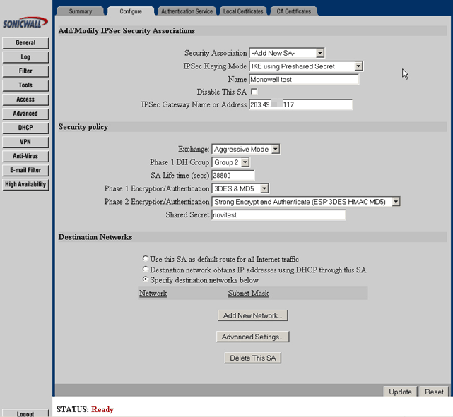
Click Add New Network
You will get: Edit VPN Destination Network (Note: This is Popup window – enable Popup in your browser)
Network: type your destination network (192.168.200.0)
Subnet mask: Type destination subnet mask (255.255.255.0)
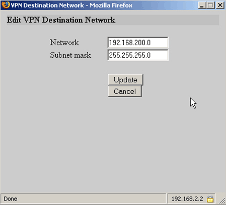
Click Update
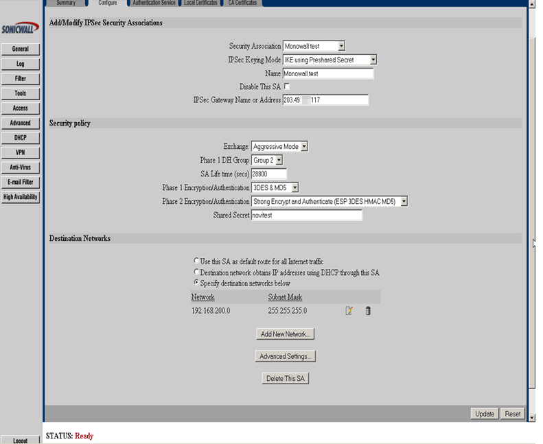
Configure m0n0wall IPsec Edit Tunnel screen as follows.
Interface: WAN
Local subnet: LAN subnet
Remote subnet: 192.168.2.0/24
Remote gateway: 61.95.x.99
Description: Sonicwall
Negotiation mode: Aggressive
My identifier: My IP address
Encryption algorithm: 3DES
Hash algorithm: MD5
DH key group: 2
Lifetime: 28800
Pre-shared key: novitest
Protocol: ESP
Encryption algorithms: 3DES
Hash algorithms: MD5
PFS key group: off
Lifetime: 28800
Click Save at the bottom of the page to complete the VPN configuration.
If you go to Nortel's support site, they have a number of documents available on setting up peer to peer IPsec tunnels using pre-shared key authentication. Find the appropriate one for your device, and set up the m0n0wall end with the appropriate settings as described in the Nortel documentation.
This tutorial tries to explain how to setup mobile user IPsec VPN with m0n0wall and Windows clients that use SafeNet SoftRemoteLT, a popular IPsec VPN client. You need m0n0wall pb25 or later for mobile user VPN.
Log into your m0n0wall and go to the IPsec: Mobile clients page.
-
Configure the settings as shown in the following picture:
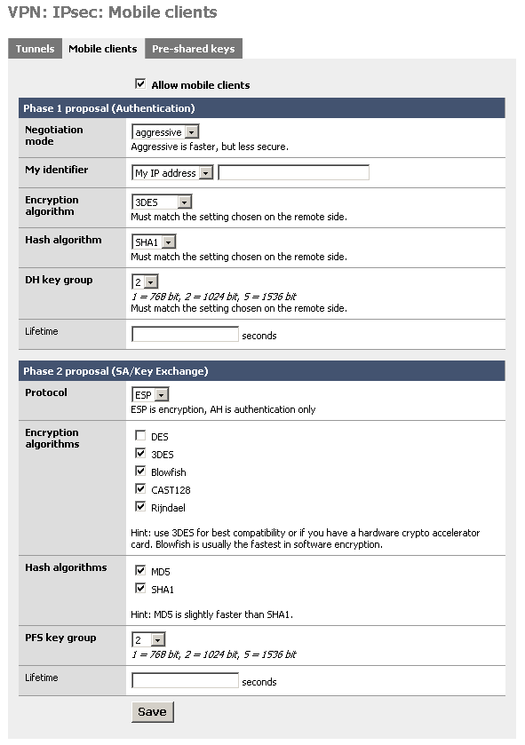
You must use aggressive mode, as only IP addresses can be used as identifiers in main mode.
Click "Save", then go to the IPsec: Pre-shared keys page.
Add a new key for each mobile user (use different keys, and at least 8 characters!). Use the e-mail address of the corresponding user as the identifier.
Go to the IPsec: Tunnels page, check "Enable IPsec" and click "Save".
This example assumes version 10 of SafeNet SoftRemoteLT.
Install SafeNet SoftRemoteLT, if not already installed, and reboot.
Right-click on the SoftRemote icon next to the clock and select "Security Policy Editor".
Choose Edit -> Add -> Connection.
-
Configure the connection properties as follows:

Insert your LAN subnet + mask and enter the external IP address (or hostname) of your m0n0wall instead of "12.34.56.78".
-
Select "Security Policy" and use the following settings:

-
Select "My Identity" and use the following settings:
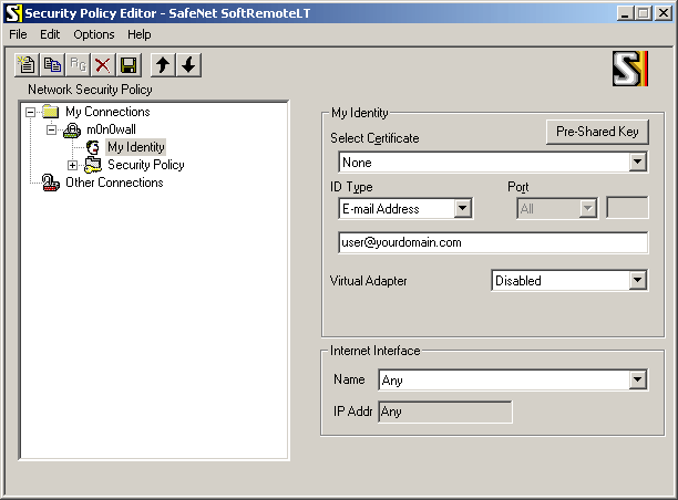
Enter the user's e-mail address, then click the button "Pre-Shared Key" and enter the pre-shared key. The e-mail address (and pre-shared key) must correspond with an entry on the IPsec: Pre-shared keys page on m0n0wall.
-
Select "Authentication (Phase 1) -> Proposal 1" and use the following settings:
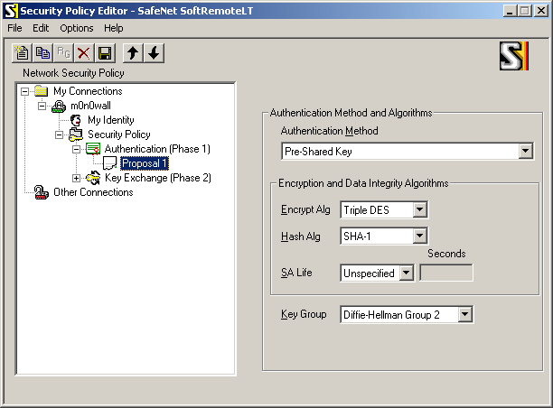
-
Select "Key Exchange (Phase 1) -> Proposal 1" and use the following settings:
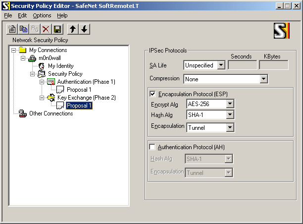
If you have a crypto accelerator card in your m0n0wall, you may want to use Triple DES instead of AES-256 as the encryption algorithm (some crypto accelerators do not support AES).
Choose File -> Save.
If you have a crypto accelerator card in your m0n0wall, you may want to use Triple DES instead of AES-256 as the encryption algorithm (some crypto accelerators do not support AES).
Choose File -> Save.
Make sure that the Internet connection is established. Try to ping a host on your LAN (e.g. your m0n0wall's LAN IP address). The first few pings will time out as it takes a few seconds for the IPsec tunnel to be established. Use SoftRemote's log viewer and connection monitor to tell you what's going on (right-click on the SoftRemote icon next to the clock to open them).
Table of Contents
- 15.1. How do I setup mobile user VPN with IPsec?
- 15.2. How can I prioritize ACK packets with m0n0wall?
- 15.3. Why isn't it possible to access NATed services by the public IP address from LAN?
- 15.4. I enabled my PPTP server, but am unable to pass traffic into my LAN
- 15.5. I just added a new interface to my m0n0wall box, and now it doesn't show up in the webGUI!
- 15.6. Does m0n0wall support MAC address filtering?
- 15.7. Does m0n0wall support SMP systems?
- 15.8. Why can't hosts on a NATed interface talk to hosts on a bridged interface?
- 15.9. What were the goals behind the m0n0wall project?
- 15.10. How do I setup multiple IP addresses on the WAN interface?
- 15.11. Can I filter/restrict/block certain websites with m0n0wall?
- 15.12. Why are some passwords stored in plaintext in config.xml?
- 15.13. Are there any performance benchmarks available?
- 15.14. What about hidden config.xml options?
- 15.15. Why can't I query SNMP over VPN?
- 15.16. Can I use m0n0wall's WAN PPTP feature to connect to a remote PPTP VPN?
- 15.17. Can I use multiple WAN connections for load balancing or failover on m0n0wall?
- 15.18. Can I access the webGUI from the WAN?
- 15.19. Can I access a shell prompt?
- 15.20. Can I put my configuration file into the m0n0wall CD?
- 15.21. How can I monitor/graph/report on bandwidth usage per LAN host?
- 15.22. Will there ever be translated versions of m0n0wall? Can I translate m0n0wall into my language?
- 15.23. Does m0n0wall support transparent proxying?
- 15.24. Should I use m0n0wall as an access point?
- 15.25. Why am I seeing traffic that I permitted getting dropped?
- 15.26. How can I route multiple subnets over a site to site IPsec VPN?
- 15.27. How can I block/permit a range of IP addresses in a firewall rule?
- 15.28. Why does my MSN Messenger transfer files very slowly when using traffic shaper?
- 15.29. Can I forward broadcasts over VPN for gaming or other purposes?
- 15.30. How can I use public IP's on the LAN side? Or how can I disable NAT?
- 15.31. Are PCMCIA cards supported?
- 15.32. Are there any tweaks for systems that will need to support large loads?
- 15.33. Can I add MRTG or some other historical graphing package to m0n0wall?
- 15.34. Can Captive Portal be used on a bridged interface?
- 15.35. Can I run Captive Portal on more than one interface?
- 15.36. Why do my SSH sessions time out after two hours?
- 15.37. Why isn't the reply address of the list set to the list?
- 15.38. Why am I seeing "IP Firewall Unloaded" log/console messages?
- 15.39. Why can't my IPsec VPN clients connect from behind NAT?
- 15.40. Why doesn't m0n0wall have a log out button?
- 15.41. Can I have more than 16 simultaneous PPTP users?
- 15.42. Can I sell m0n0wall (or use it in a commercial product)?
- 15.43. Where can I get a high-resolution version of the m0n0wall logo?
- 15.44. When will m0n0wall be available on a newer FreeBSD version?
- 15.45. Is there any extra Captive Portal RADIUS functionality available?
- 15.46. How can I increase the size of the state table?
Everything you ever wanted to know about m0n0wall but were afraid to ask. This is a must-read before posting questions to the mailing list!
This tutorial tries to explain how to setup mobile user IPsec VPN with m0n0wall and Windows clients that use SafeNet SoftRemoteLT, a popular IPsec VPN client. You need m0n0wall pb25 or later for mobile user VPN.
Log into your m0n0wall and go to the IPsec: Mobile clients page.
-
Configure the settings as shown in the following picture:
You must use aggressive mode, as only IP addresses can be used as identifiers in main mode.
Click "Save", then go to the IPsec: Pre-shared keys page.
Add a new key for each mobile user (use different keys, and at least 8 characters!). Use the e-mail address of the corresponding user as the identifier.
Go to the IPsec: Tunnels page, check "Enable IPsec" and click "Save".
This example assumes version 10 of SafeNet SoftRemoteLT.
Install SafeNet SoftRemoteLT, if not already installed, and reboot.
Right-click on the SoftRemote icon next to the clock and select "Security Policy Editor".
Choose Edit -> Add -> Connection.
-
Configure the connection properties as follows:
Insert your LAN subnet + mask and enter the external IP address (or hostname) of your m0n0wall instead of "12.34.56.78".
-
Select "Security Policy" and use the following settings:
-
Select "My Identity" and use the following settings:
Enter the user's e-mail address, then click the button "Pre-Shared Key" and enter the pre-shared key. The e-mail address (and pre-shared key) must correspond with an entry on the IPsec: Pre-shared keys page on m0n0wall.
-
Select "Authentication (Phase 1) -> Proposal 1" and use the following settings:
-
Select "Key Exchange (Phase 1) -> Proposal 1" and use the following settings:
If you have a crypto accelerator card in your m0n0wall, you may want to use Triple DES instead of AES-256 as the encryption algorithm (some crypto accelerators do not support AES).
Choose File -> Save.
If you have a crypto accelerator card in your m0n0wall, you may want to use Triple DES instead of AES-256 as the encryption algorithm (some crypto accelerators do not support AES).
Choose File -> Save.
Make sure that the Internet connection is established. Try to ping a host on your LAN (e.g. your m0n0wall's LAN IP address). The first few pings will time out as it takes a few seconds for the IPsec tunnel to be established. Use SoftRemote's log viewer and connection monitor to tell you what's going on (right-click on the SoftRemote icon next to the clock to open them).
On asymmetric Internet links like DSL and often Cable, a big upload that consumes all of the available upstream bandwidth can render the link almost unusable by producing a huge backlog in the DSL/Cable modem's buffer, thus increasing the delay to several seconds. Because ACK packets (TCP acknowledgments) for received data are delayed or even lost as well, download speed drops, too.
This problem can be solved by prioritizing these ACK packets, so they will be sent out before any other upload packets. Here's how to do it with m0n0wall:
First of all, you need m0n0wall pb24 or later. Start by adding a new pipe to the traffic shaper. This is necessary because we need to move the upstream queue into m0n0wall (where the order in which packets are sent out can be changed while packets are in the queue) rather than the DSL/Cable modem. Once the packets are in the DSL/Cable modem's output queue, there's no way of having ACK packets sent out immediately anymore. Therefore, it is very important to set that pipe's bandwidth to a value that is slightly below the effective upstream bandwidth of your Internet link. Don't forget that e.g. 128 kbps ADSL line speed is only about 100 kbps effective. If you set this value too high, your modem buffer will still become full and prioritization will accomplish nothing.
When you have added that pipe, add two queues linked to that pipe with different weights, e.g. one queue with weight = 10 and one with weight = 1. The first queue becomes your high priority queue.
Now it's time to add rules that classify upstream traffic into one of these two queues. There are loads of possibilities, e.g. prioritizing by TCP/UDP port, but for now we'll focus on IP packet length and TCP flags. Add a new traffic shaper rule, link it to the first (high-priority) queue, interface = WAN, protocol = TCP, source = any, destination = any, direction = out, IP packet length 0-80, TCP flags: ACK = set, everything else = don't care. It is not sufficient to classify packets into the high-priority queue based on the ACK flag only, because (big) upstream TCP data packets can have the ACK flag set as well. 0-80 is just an example to get you started. Save the rule, and add another one below it, linked to the second (low priority) queue, interface = WAN, protocol = any, source = any, destination = any, direction = out. Enable the traffic shaper if necessary, apply the changes - that's it. Here are a few points to remember:
make sure no upstream Internet traffic can bypass the pipe
despite ACK prioritization, the delay will still go up, as it is not possible to stop sending a big packet mid-way. For example, a full-size (1500 bytes) packet at 100 kbps will take 120 ms
if you want to be able to surf the web while performing a large upload, you'll also have to prioritize HTTP upstream traffic (i.e. destination port = 80) - otherwise, TCP SYN packets (for connection establishment) to web servers will not get prioritized, and there will be a big initial delay until a connection is established. Prioritizing DNS packets is a good idea as well.
If you want to find out what prioritization does for you, add a rule to classify outgoing ICMP packets into the high-priority queue and try pinging some Internet host while you're uploading - once with the traffic shaper on, and once off. There should be a huge difference in response times.
Problem. It is not possible to access NATed services using the public (WAN) IP address from within LAN (or an optional network). Example: you've got a server in your LAN behind m0n0wall and added a NAT/filter rule to allow external access to its HTTP port. While you can access it just fine from the Internet, you cannot access http://your-external-ip/ from within your LAN.
Reason. This is due to a limitation in ipfilter/ipnat (which are used in m0n0wall). Read the ipfilter FAQ for details. m0n0wall does not (and probably will not) include a "bounce" utility.
Solution. If you use m0n0wall's built-in DNS forwarder for your LAN clients, you can add one or more overrides so that they will get the internal (LAN) IP address of your server instead of the external one, while external clients still get the real/public IP address.
Note
This will only work if you use m0n0wall as the primary DNS server on your LAN hosts. If you use another DNS server, you need to use its functionality to resolve that host to the appropriate private IP. See your DNS server documentation for more information.
You neglected to create a firewall rule to allow this traffic.
Go to Firewall Rules and add a rule on the PPTP interface to permit traffic from PPTP clients. (ex: interface PPTP, protocol any, source PPTP clients, destination any)
Traffic should now pass through the interface correctly.
You probably forgot to assign a function to the interface. Use the console menu's "assign network ports" option to do that.
Short answer: Not yet. (i.e. you cannot specify MAC addresses in firewall rules)
Long answer: There are several "hacks" you may be able to use to achieve the desired end result.
Note
There is no bulletproof method of access control by MAC address. Keep in mind that MAC addresses are easy to change and spoof.
You can utilize Captive Portal and its MAC pass-through functionality for rudimentary MAC address restrictions.
Enable Captive Portal on the desired interface (e.g. LAN) at the Services -> Captive Portal screen. Create a HTML page of your liking that does not include the submit button so the user cannot authenticate with the captive portal. Other settings can all be left at their defaults.
Click the "Pass-through MAC" tab on the Captive Portal screen. Click the + to start adding permitted MAC addresses. In the MAC address box, type in the six hex octets separated by colons (e.g. ab:cd:ef:12:34:56), optionally (but recommended) enter a description, and click Save. Repeat for every authorized host on your network.
First, set up your DHCP scope. At the bottom of the Services -> DHCP screen, add every authorized MAC address on your network, and check the "Deny unknown clients" box. This will prevent an unauthorized machine from getting an IP address from DHCP.
You can ensure certain MAC addresses can only use a certain IP by using static ARP.
To add a static ARP entry, use /exec.php to run the arp command.
arp -s 192.168.1.11 ab:cd:ef:12:34:56
To verify this addition, run 'arp -a' in exec.php and you'll see the following in the list.
? (192.168.1.11) at ab:cd:ef:12:34:56 on sis2 [ethernet]
This change will not survive a reboot. You need to put the arp -s command in your config.xml in <shellcmd>. See this FAQ entry for more information on hidden config.xml options
Note
An unauthorized user with a clue will be able to get around this second method more easily than the first method by just assigning a static IP address that isn't in use. Either method is easy enough to get around for a user with a decent amount of knowledge.
SMP support isn’t built in to m0n0wall, and the current versions have no add-on SMP support available. m0n0wall will run on SMP systems, however it will only utilize one processor.
Note
Michael's SMP support hasn't been updated in quite some time, and will not work with current m0n0wall releases.
Michael Iedema has written a program to automatically add SMP support to a m0n0wall release, which is available from http://www.michael-i.com/files/projects/m0n0smp.
The script requires pseudo-device
vn built into your kernel. When first run, it downloads
the latest SMP kernel from Michael’s site and updates the image. The
--update flag will re-download the SMP kernel in the event that Michael
releases a new revision of the kernel. Michael also has a pre-built copy
of the latest generic-pc image with SMP available for download from his
page.
This frequently happens when someone wants to bridge an interface to their WAN to use it as a DMZ, and wants to put all of the hosts on their LAN interface behind a NAT. This is actually a fairly reasonable and natural thing to want to do.
The problem here is that ipnat and bridging (at least as implemented in FreeBSD) don't play well together. Packets from the LAN to the DMZ go out just fine, but in the other direction, it seems like the packets arriving on the unnumbered bridge interface don't get looked up correctly in the ipnat state tables.
I've managed to convince myself that solving this is Really Really Hard (TM). The irritating thing is that there's no theoretical reason why this should be difficult...it all comes down to implementation details.
Contribution from Bruce A. Mah <bmah (at) freebsd.org>
Back in January 2004, Manuel, the guy behind m0n0wall, posted the following to the m0n0wall mailing list,
Hey folks,

I feel the need to state once and for all what the intention with which
I started m0n0wall was. My goal was to create a free/open-source
alternative to smaller commercial firewall boxes - no more, no less. I
figured that on a Soekris or similar embedded PC, it could be made to
look and behave just like a commercial firewall - only cheaper and with
me in control of the features. When I started working on it, I
especially had the following models in mind:

- WatchGuard SOHO
- ZyXEL ZyWALL 10
- SonicWALL SOHO
- NetScreen 5XP

I didn't intend to create an enterprise-class firewall, and I didn't
intend to make a file, mail, print, web or whatever server. And despite
the fact that m0n0wall runs well (and in the majority of installations,
according to the survey!) on normal PCs, it is targeted at embedded PCs,
which means they dictate what is possible in terms of storage, CPU speed
and RAM size.

I think m0n0wall mostly meets or even exceeds the feature range of the
aforementioned products, so my goal has already been reached. That
doesn't mean there's no room for or point in improvements. I just want
to make it clear that I don't think we're ever going to see things like
the following in m0n0wall:

- caching proxy
- file server (Samba etc.)
- mail server
- web server (Apache etc.)
- very extensive statistics

simply because it wasn't my goal to produce some all-in-one thing like
e-smith, but a packet filtering firewall. Furthermore, these things
usually don't mix well with embedded PCs for several reasons.

Why do we have a DHCP server then? Because all the commercial products I
mentioned before do, because it's small and lightweight enough to fit in
with the rest, and because it considerably increases ease-of-use
(meaning that if your Internet connection uses DHCP too, like for
example cable, you don't have to configure anything at all to let your
clients access the Internet - that's why it's on by default too).

Now, about the NTP server... Rest assured that if msntp didn't have
problems with Windows XP clients, there would have been a nice little
NTP server configuration page in the webGUI, or at least a checkbox on
the general setup page (with default to off of course), since pb15. But
I don't like stuff that works only half of the time, so that's why it
hasn't happened yet.

There you go... Hope I've explained my point of view now.

Regards,

Manuel
Although the m0n0wall webGUI only allows setting up a single IP address on the WAN interface, you can still have m0n0wall accept packets destined to secondary IP addresses. It is not necessary to tell m0n0wall to use these IP addresses on the WAN interface (however in some cases proxy ARP has to be used - see below), but you have to tell it what to do with packets that are sent to them. There are two possibilities:
-
Routing
You can use this if you have an entire subnet of public IP addresses (with m0n0wall's WAN IP address not being in that subnet!).
Example: you have several servers connected to an optional interface (let's assume OPT1). Choose an IP address out of your public subnet for m0n0wall's IP address on OPT1. Use it as the default gateway on all the servers connected to OPT1 (it goes without saying that you assign public IP addresses directly to the servers on OPT1 in this scenario). Make sure to get the subnet mask right on m0n0wall and the OPT1 servers. Turn on advanced outbound NAT and define a rule for your LAN, but not for OPT1. This will effectively disable NAT between WAN and OPT1. Now you can add filter rules to selectively permit traffic to/from OPT1.
-
NAT
-
inbound/server NAT
Use this if you want to redirect connections for different ports of a given public IP address to different hosts (define one or more of your secondary IP addresses for server NAT, then use them with inbound NAT as usual).
-
1:1 NAT
Use this if you have enough public IP addresses for all your servers, but can't use routing because you don't have a whole subnet.
-
advanced outbound NAT
Use this if you want to take control over the IP addresses that are used for outgoing connections from machines that don't have 1:1 mappings (by default, m0n0wall's WAN IP address is used).
-
If any of the following applies to your setup, you should be fine without proxy ARP:
the additional IP addresses that you're trying to use are part of a subnet that is routed to you by your ISP (i.e. your ISP has a static route for that subnet with your m0n0wall's WAN IP address as the gateway)
you're using PPPoE or PPTP on WAN
Using proxy ARP under these conditions will not achieve anything. If however you use static IP addresses or DHCP on WAN and don't have a routed subnet, adding proxy ARP entries for the additional addresses/ranges/subnets in the webGUI will make sure that m0n0wall responds to ARP queries for these addresses on the WAN interface.
Adding Proxy ARP when it is not required usually will not hurt anything, so when in doubt, add it!
Note
Do not add Proxy ARP entries for IP addresses that are not assigned to you! Most DHCP servers will attempt to do an ARP query before assigning an IP address to a client, and if you enable Proxy ARP on IP's that are not yours, they will appear to be in use to the DHCP server. We have heard of instances where people enabled Proxy ARP for their entire WAN subnet, and got disconnected because they were "taking up all the DHCP addresses." Technically you aren't taking all the leases, you're just answering ARP on all of them which is just as bad. This is typically only an issue when your WAN is an Ethernet network, but don't ever do it.
Note that it is never necessary (and strongly discouraged) to use IP aliasing on the WAN interface (by means of ifconfig commands).
There are no filtering capabilities built into m0n0wall based on web site content, keywords, etc., nor any supported add-ons with such functionality.
Blocking by IP Address/Subnet
You can block specific sites by putting in firewall rules to deny access to the undesired server's IP address. If you take this path, it is recommended you use "reject" rather than "block" in the firewall rules so inaccessible sites time out immediately.
Blocking by DNS Override
If you use your m0n0wall as your only DNS server, you can also block specific sites by putting in DNS override for the undesired site to point to an internal or invalid IP address. To block www.example.com, put in a DNS override pointing it to 1.2.3.4 or some other invalid IP address, or an address of a LAN web server. If you use an invalid IP address, you should put in a firewall rule to reject packets to this address so the requests time out immediately.
Note this is easy to get around by either using a different DNS server or editing the hosts file on the local machine, though this is beyond the capabilities and knowledge of most any user.
Using a Proxy Server
The ideal solution would be to use a proxy server on your LAN, and block outgoing traffic from your LAN hosts other than the proxy server.
PPPoE/PPTP client, PPTP VPN, and DynDNS passwords as well as RADIUS and IPsec shared secrets appear in plaintext in config.xml. This is a deliberate design decision. The implementations of PPP, IKE, RADIUS and the way DynDNS works require plaintext passwords to be available. We could of course use some snake oil encryption on those passwords, but that would only create a false sense of security. Since we cannot prompt the user for a password each time a PPP session is established or the DynDNS name needs to be updated, any encryption we apply to the passwords can be reversed by anyone with access to the m0n0wall sources - i.e. everybody. Hashes like MD5 cannot be used where the plaintext password is needed at a later stage, unlike for the system password, which is only stored as a hash. By leaving the passwords in plaintext, it is made very clear that config.xml deserves to be stored in a secure location (or encrypted with one of the countless programs out there).
Some m0n0wall options are only accessible by modifying config.xml directly. This is usually the case for strange/exotic options that only few people (should) use. Instead of cluttering the webGUI with lots of options that almost nobody really uses, they can only be set in config.xml. For the ultimate reference on all available options in config.xml, see the latest default config.xml available at http://m0n0.ch/wall/downloads/config.xml. Not all of these options may be available unless you're using the latest beta.
To put in these options, download your config.xml via the backup feature and open it in a text editor. Put in the desired options in the appropriate location in the file, as shown in the default config.xml linked above. After saving your desired changes, use the restore feature in m0n0wall to restore the changed configuration.
Some options are documented below:
-
system/webgui/noassigninterfaces
hides the "assign interfaces" link in the navigation bar
-
system/earlyshellcmd and system/shellcmd
may contain a shell command that is executed before the boot scripts actually start setting up the system (for earlyshellcmd), or after the boot scripts have finished setting up the system (for shellcmd). You can have multiple (early)shellcmd tags. Don't forget to replace special characters with their XML equivalents (most notably < and > (< and >).
-
interfaces/(if)/media and interfaces/(if)/mediaopt
If you need to force your NIC to a specific media type (e.g. 10Base-T half duplex), you can use these two options. Refer to the appropriate FreeBSD manpage for the driver you're using to see which options are available (or run ifconfig -m).
-
dhcpd/(if)/gateway
Allows you to specify a custom gateway to assign to DHCP clients (instead of m0n0wall's IP address on the corresponding interface)
-
dhcpd/(if)/domain
Assigns a custom domain name to DHCP clients (instead of the one configured on System: General setup)
-
dhcpd/(if)/dnsserver
Assigns custom DNS servers to DHCP clients (instead of m0n0wall's IP address if the DNS forwarder is enabled, or the DNS servers configured on System: General setup otherwise)
-
dhcpd/(if)/next-server and dhcpd/(if)/filename
These are used for PXE booting, and you should know what they do if you're trying to set up PXE.
With an out of the box configuration, you cannot query SNMP on the LAN interface of a remote m0n0wall over a VPN connection. Fred Wright explained in a post to the mailing list on September 12, 2004 why this is.
Due to the way IPsec tunnels are kludged into the FreeBSD kernel, any
traffic *initiated* by m0n0wall to go through an IPsec tunnel gets the
wrong source IP (and typically doesn't go through the tunnel at all as a
result).  Theoretically this *shouldn't* be an issue for the *server* side
of SNMP, but perhaps the server has a bug (well, deficiency, at least)
where it doesn't send the response out through a socket bound to the
request packet.

You can fake it out by adding a bogus static route to the remote end of
the tunnel via the m0n0wall's LAN IP (assuming that's within the near-end
tunnel range).  A good test is to see whether you can ping something at
the remote end of the tunnel (e.g. the SNMP remote) *from* the m0n0wall.

There's an annoying but mostly harmless side-effect to this - every LAN
packet to the tunnel elicits a no-change ICMP Redirect.
To do this, click "Static Routes" in the webGUI. Click the + to add a static route. In the Interface box, choose LAN, for destination network, enter the remote end VPN subnet, and for the gateway put in the LAN IP address of your local m0n0wall.
The m0n0wall WAN PPTP feature is for ISP's that require you to connect using PPTP (some in Europe require this).
This feature cannot be used as a PPTP client to connect to a remote PPTP server to allow m0n0wall to route over the PPTP connection.
Not in a default configuration. This is disabled for security reasons.
To enable this, first switch to SSL if you haven't already. To do so, go to System -> General Setup, and change webGUI protocol from HTTP to HTTPS.
Note
You may need to change the port number used by the webGUI. If you have used inbound NAT to open HTTPS to a web server, you'll have to change that port number to something other than the default 443, and change the destination port on the firewall rule shown below accordingly.
Now click Firewall -> Rules and click the ![]() on that screen. Add a rule like the following,
replacing the made up IP 12.221.133.125 with the public IP of the remote
system you wish to use to administer your m0n0wall, and 64.22.12.25 with
the public IP of your m0n0wall.
on that screen. Add a rule like the following,
replacing the made up IP 12.221.133.125 with the public IP of the remote
system you wish to use to administer your m0n0wall, and 64.22.12.25 with
the public IP of your m0n0wall.
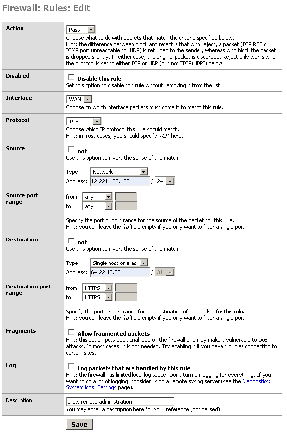
This makes things a little trickier. You can't set the destination IP because it will change, and when it changes you would no longer be able to get to the webGUI. You can set the source to "any" rather than the WAN IP. Note that this will grant access to anything with an inbound NAT entry for the port (likely HTTPS), or anything behind a bridged interface with a public IP on that port. Unless you have multiple public IP's, this will not grant access to anything other than the webGUI. This does not grant that host access to HTTPS for anything on your LAN. Even if you do have multiple public IP's, opening HTTPS to a host you intend to allow to configure your firewall is likely of little to no concern.
Note
Opening your webGUI to the entire internet is a bad idea. Limit it to only the IP address required. If the remote administration host is on DHCP, you can limit it to the remote machine's ISP's netblock rather than opening it to the entire internet. Opening your firewall administration interface to the entire internet, even with strong authentication, is strongly discouraged on any firewall.
There is no true shell prompt per se in m0n0wall, and no supported way to add one. You can get some limited shell functionality by going to the hidden /exec.php page.
Yes, but keep in mind this means you will need to burn a new CD any time you want to change anything on the configuration.
To do this, replace the file /conf.default/config.xml on the iso with your config.xml file.
John Voigt posted the a way to accomplish this to the m0n0wall mailing list on September 22, 2004.
Chris Buechler is working on making this more understandable and easier to follow. You can see the work in progress on the wiki here for now.
The short answer is: no.
The long answer is: the author of m0n0wall has decided that translations add an extreme amount of overhead, since each time a new feature is developed (or an existing feature is modified), all the translators need to be contacted to get the proper translations for the new strings. Experience shows that people are often eager to start something new, but lose interest and give up or go away after a while, so it'd be hard to keep all the different languages synchronized. Failure to do so would lead to incomplete or mixed (with English) translations - something which immediately creates a very bad impression in most users. Furthermore, translating the interface of a firewall isn't as easy as it seems - the translator needs to fully understand all the concepts that are involved in order to produce accurate translations.
Side note: the native language of the author of m0n0wall is not English either. However, he believes that anyone who's trying to accomplish anything non-trivial with a firewall, especially an open source one, will never get around learning English anyway.
That said, everybody's free to start their own (translated) m0n0wall branch - the BSD license, under which m0n0wall is placed, essentially permits anyone to do anything with m0n0wall as long as the original copyright notice and license are preserved somewhere (see the license for details). It should be made clear that it's not an "official" version though.
Currently it does not. The following was taken from a post by Manuel Kasper, m0n0wall's author, in a post to the mailing list on October 5, 2004.
I think this is very appropriate, but the reason why it hasn't
happened yet is that nobody has figured out how to do it yet. ;) The
problem always seems to be how to tell the proxy which IP
address/port the user initially tried to connect to. But that may not
even be necessary (HTTP Host header). If a clean solution with
ipfilter/ipnat is possible, that would be cool.
Manuel Kasper, author of m0n0wall, posted the following to the m0n0wall mailing list on December 29, 2004.
If you want to be really happy with your wireless, then by all means
buy a real dedicated AP. hostap just never matches the performance
and reliability (not even under Linux) of a *good* AP, and is only
intended as a solution for people who absolutely need to do
everything on one box.
Chris Buechler has this to add:
I have a 2511MP+ in my 4501, though honestly, I don't use it
much anymore for anything other than m0n0wall testing.  I got
a Linksys WRT54G to use for wireless.  FreeBSD 4.11's hostap
just plain sucks IMO.  It's starting to show its age (the 4.x
version is several years old).  There are many newer cards
you just can't get to connect to it no matter what (more than
half the b/g and a/b/g cards I've tried), some that require
configuration changes to connect, and in general it's just
a pain.  Given the cost of miniPCI cards, a Linksys or
similar is a good alternative for about the same cost - just
bridge the wireless over to an OPT port on m0n0wall, as I do.

Things should improve very much in the next m0n0wall version,
including support for a/b/g cards and none of the pains of
4.11's dated hostap, so you may want to hold off for a few
months or so if you can.
Assuming your firewall rules are set up appropriately to allow this traffic, the reason is because they are duplicate or last packets of a session. This is explained as follows by the IPFilter howto.
Due to the often laggy nature of the Internet, sometimes packets will be regenerated. Sometimes, you'll get two copies of the same packet, and your state rule which keeps track of sequence numbers will have already seen this packet, so it will assume that the packet is part of a different connection. Eventually this packet will run into a real rule and have to be dealt with. You'll often see the last packet of a session being closed get logged because the keep state code has already torn down the connection before the last packet has had a chance to make it to your firewall. This is normal, do not be alarmed.
There are two ways to accomplish this. Which is most suitable depends on if you are able to summarize the subnets, and how many subnets are involved. For either way, the subnets do not need to be directly connected to m0n0wall. They can be behind a router on the LAN behind m0n0wall. In that case, you'll need to set up static routes on m0n0wall's LAN interface pointing to the LAN router for each of the subnets in question. You can also summarize the subnets in static routes.
If you are using, for example, 192.168.1.0/24 at one site, and the other site uses 10.0.0.0/24, 10.0.1.0/24, 10.0.2.0/24, and 10.0.3.0/24, you can summarize the 10.x.x.x site with 10.0.0.0/22. 10.0.0.0/22 includes 10.0.0.0-10.0.3.255.
You can set up one IPsec connection for each subnet you want to connect to on the remote side. If you have a large number of subnets on the remote side, it is recommended you number them so they're easily summarized so you don't have to set up a large number of connections.
If you can summarize the IP addresses with a CIDR mask, you can enter a rule to apply to those hosts. For example, 10.0.0.8-10.0.0.15 can be summarized with 10.0.0.8/29.
Because the traffic shaping rules to limit BitTorrent throughput cover the same range of ports MSN uses. Magic Shaper uses 6881-6999 to classify BitTorrent traffic, which encompasses the MSN ports 6891-6900. You can change the rules that classify BitTorrent traffic in the traffic shaping pages. Typically BitTorrent only uses 6881-6889.
Credit: Chris Bagnall
Not yet. OpenVPN will make this possible in the future.
If you're using public IP's on your LAN, or need to disable NAT for some other reason, enable advanced outbound NAT, under Firewall -> NAT, Outbound tab.
The drivers are available for most PCMCIA cards, however FreeBSD 4.x typically doesn't work out of the box with PCMCIA cards. Wireless cards are generally an exception, but this might also be the case for some. Some customization to /etc/pccard.conf is typically required for the card to be detected. Google for your card model and FreeBSD and pccard.conf to find the required values if the card is not detected. You'll have to edit your m0n0wall image appropriately.
You may need to up the kern.ipc.nmbclusters sysctl. If you are getting "out of mbuf" errors, this will fix that.
From 'man tuning':
    kern.ipc.nmbclusters may be adjusted to increase the number of network
    mbufs the system is willing to allocate.  Each cluster represents approx-
    imately 2K of memory, so a value of 1024 represents 2M of kernel memory
    reserved for network buffers.  You can do a simple calculation to figure
    out how many you need.  If you have a web server which maxes out at 1000
    simultaneous connections, and each connection eats a 16K receive and 16K
    send buffer, you need approximately 32MB worth of network buffers to deal
    with it.  A good rule of thumb is to multiply by 2, so 32MBx2 = 64MB/2K =
    32768.  So for this case you would want to set kern.ipc.nmbclusters to
    32768.  We recommend values between 1024 and 4096 for machines with mod-
    erates amount of memory, and between 4096 and 32768 for machines with
    greater amounts of memory.  Under no circumstances should you specify an
    arbitrarily high value for this parameter, it could lead to a boot-time
    crash.  The -m option to netstat(1) may be used to observe network clus-
    ter use.  Older versions of FreeBSD do not have this tunable and require
    that the kernel config(8) option NMBCLUSTERS be set instead.
Add a line like the following to the /boot/loader.rc on the image.
set kern.ipc.nmbclusters=32768
That would take 64 MB RAM. With 128+ MB RAM and m0n0wall, you could set it to that or higher, but setting it arbitrarily high may cause problems as stated above.
The default on FreeBSD and m0n0wall is 1024, which is fine unless you require a huge number of connections. It's set to 1024 by default to limit memory consumption, and 1024 is more than enough for the vast majority of m0n0wall installations.
Or "why SVG, it doesn't tell me anything". Not true, there are many uses for real time graphing data that MRTG, ifgraph and similar historical packages cannot provide. These fill two different needs.
Not directly on the firewall. These packages all have heavy requirements like Perl and others. In order to keep m0n0wall light, these packages cannot be added directly to the system. m0n0wall's file system design, in that it runs from RAM and does not maintain anything other than your configuration across reboots, is not condusive to applications of this nature.
You can run these from another system on your network. See ifgraph section of this guide.
No. Because of the way Captive Portal is implemented, it cannot function on a bridged interface.
No. Because of the way Captive Portal is implemented, it cannot be used on more than one interface.
As of 1.2b2, the TCP idle timeout for the firewall is 2.5 hours instead of the ipfilter default of 10 days (!) to keep the state table from filling up with dead connections. This value can be modified on the advanced setup page, though that is not recommended. So of course if your SSH connection doesn't transfer a single byte for two hours, the ipfilter state table entry is deleted and the connection breaks. Turning on keep-alives in your SSH client is the recommended means of avoiding broken sessions.
The ezmlm FAQ explains why this is not recommended.
Manuel posted the following explanation to the list on May 12, 2003.
It will stay this way because I read this:
http://www.ezmlm.org/faq-0.40/FAQ-9.html#ss9.8
and found that they're right - I can live with the fact that people have
to think twice before posting anything to the list. :) Besides, other
lists behave in the same way, too (including soekris-tech and
freebsd-small), and every better MUA has got a "Reply All" function, so
that issue is settled as far as I'm concerned.
Also see The Great Reply-to Debate in the book Producing Open Source Software.
Nothing to worry about. ipfw is only used for traffic shaping in m0n0wall - you probably enabled and later disabled the traffic shaper (the module is only loaded on demand). The real packet filtering is done with ipfilter, which is compiled into the kernel and cannot be unloaded.
That's because FreeBSD doesn't support NAT-T, which is required for IPsec to work behind NAT on the remote end.
Unfortunately, there's no way to fix that at this point. OpenVPN, which is in the current beta versions, might be a good solution.
m0n0wall uses HTTP authentication. For every page you request from m0n0wall, your browser sends the username and password from its cache. There is no reliable way to force the browser to "forget" the username and password, and session management to work around that would introduce potential security vulnerabilities, so m0n0wall does not provide log out functionality. To safely log out, close your browser.
Your web browser may have a way to clear cached HTTP credentials. Check your browser's documentation for further information.
Yes, though this is not officially supported. See this page on Chris Buechler's website for images and further information.
m0n0wall is under the BSD license, which basically means that you can do whatever you want with it (including modifying and selling it) for free, as long as the original copyright notice and license appear somewhere in the documentation and/or the software itself. There are no warranties of any kind though.
For the full copyright notice/license text, see http://m0n0.ch/wall/license.php.
Although you don't have to pay anything for m0n0wall even if you sell it, if you do find yourself making money by selling m0n0wall-based products, a donation would be very much appreciated.
An EPS version of the logo is available here.
Beta versions 1.2b5 through b7 were based on FreeBSD 5.3, after much demand. This brought greatly improved wireless card support, but that's it. Many other, more important things were a major step back from the current FreeBSD 4.x. Network performance was anywhere from 20-50% of the speed it used to be on embedded platforms, and stability was poor in comparison in some environments.
We consulted with members of the FreeBSD Core Team on the issues we were seeing with performance, and their answer was basically "yes, we know it is slower, and are working on improving it." FreeBSD 6 is already much improved, and the funded TCP optimization work currently being done will improve things much more.
It was decided to revert back to 4.x to finish the 1.2 release, and hence get it done much faster than would be possible on 5.x and with a much better end result.
After 1.2 is released, discussion will be started on the list as to which operating system and firewall software is best suited for the next m0n0wall release. At this point, FreeBSD 6 looks like the most likely candidate, and will bring back Atheros support amongst many other enhancements not available in FreeBSD 4 or 5.
Jonathan De Graeve has implemented a number of new RADIUS features for Captive Portal that will be implemented in a future beta version. For now, these features are available on test images available for download from http://inf.imelda.be/downloads/m0n0wall/.
Features currently implemented in the test images include:
RADIUS-defined URL redirection taking precedence over URL redirection parameter in captive portal setup page.
Multiple RADIUS server support
Failure message on captive portal login error page, plus logging to the captive portal log on why authentication failed (user account exceeded bandwidth limit, bad password, etc.).
Cisco-compatible feature (sending calling-station-id with clientip and called-station-id with clientmac instead of standard behavior calling-station-id and clientmac).
Timeout parameter and max authentication retries parameter
retrieval of user bandwidth settings
retrieval of user group
retrieval of session-timeout
Note
Retrieval means the variable is present and CAN be used, but there is no action bound to it yet.
To do - GUI implementation and enhancements.
m0n0wall's default firewall state table is limited to 30,000 states. This is sufficient for the vast majority of firewalls, and extra states may require more RAM than exists in some m0n0wall installations.
Unfortunately, to increase the size of the state table you have to recompile the kernel. See The complete guide to building a m0n0wall image from scratch in the m0n0wall Developers' Handbook.
Note
This is rarely necessary. Unless you have a very fast and heavily loaded Internet connection, or 10+ Mb of certain types of peer to peer traffic, chances are you will never exceed 30,000 states. The number of states required by a given environment will vary dramatically. 50 Mbps of HTTP, SMTP, POP3, and IMAP traffic might only take 20,000 states, but 50 Mbps of peer to peer traffic from dozens of machines might take more than a million states.
If you find you cannot create new connections to the Internet from any machine, but existing connections all work properly, you may have exhausted your state table.
Table of Contents
There are many people who have written additional documentation for m0n0wall which are beyond the scope of this manual, or which have not yet been incorporated into this manual. This chapter provides a reference to some of those sources to help you when you find yourself in a situation not covered in detail in this manual.
m0n0wall Live Installer - FreeBSD Live CD (built using FreeSBIE) including all m0n0wall 1.11 and 1.2b3 images and instructions on using it.
Installing m0n0wall over a network - Roberto Pereyra
Authenticating m0n0wall's PPTP VPN with an Active Directory Server - Michael Iedema
Configuring a Wireless Network to Network IPSEC bridge using m0n0wall - Michael Iedema
Wireless inSecurity (bottom of page) - Michael Iedema
Table of Contents
- 17.1. Interfaces are not detected
- 17.2. After replacing my current firewall with m0n0wall using the same public IP, m0n0wall cannot get an Internet connection.
- 17.3. No Link Light
- 17.4. Cannot Access webGUI
- 17.5. Cannot Access Internet from LAN after WAN Configuration
- 17.6. Troubleshooting Firewall Rules
- 17.7. Troubleshooting Bridging
- 17.8. Troubleshooting IPsec Site to Site VPN
- 17.9. Troubleshooting Solid Freezes
This chapter outlines some of the more common problems you may experience when using m0n0wall, and how to troubleshoot and resolve them.
Tip
To allow yourself access to log messages even if the m0n0wall device is unreachable, you can send syslog messages to a remote syslog server. This way you can see many logs that might help identify the problem. See the section on Logging for more information.
First check your BIOS settings for a "Plug and Play OS" or "OS" setting. For "Plug and Play OS", set it to "no" or "disable". If there is an "OS" setting, typically you can and should set it to "other". This most always fixes the problem.
If that doesn't resolve it, try to upgrade your system BIOS.
Resetting the BIOS to default settings might help. There have been instances in the past where this has resolved this problem, likely due to some strange BIOS setup from past use of the hardware.
Occasionally other hardware like sound cards, and similar, can prevent some or all of your cards from being detected. Try removing any cards in the system that aren't required, and disabling any unused hardware (USB, parallel port, serial ports, any onboard sound, etc.) in the system BIOS.
Most all Ethernet cards are supported by m0n0wall, but if you still cannot see the network cards, ensure they are supported.
This same problem can affect new 1:1 and Server NAT configurations.
Cause. This is typically caused by the router outside of your m0n0wall having the MAC address of your previous firewall still in its ARP table. Cisco routers, for example, will cache this for four hours by default. Many other routers are similar.
Solution
Clear the ARP cache on your router. If you don't have access to the command interface of the router, or don't know how to clear the ARP cache, power cycling the router should achieve the same result.
Alternatively, you could fill in the MAC address of the WAN interface of your previous firewall in m0n0wall's WAN interface screen.
If you do not have a link light on your network interfaces, they are not up and will not be able to communicate with the network. Your LAN and WAN interfaces both must have link lights.
If you do not have a link light on one of your network interfaces, there are a few potential causes and things to check.
Ensure the network cable is snugly plugged in on both ends. Unplug and replug the cable to ensure it is properly seated.
Try a different cable.
-
Make sure you are using the appropriate type of cable.
There are two types of standard Ethernet patch cables, straight and crossover.
Straight cables
are used to attach devices like computers, routers (ones like Cisco, not counting most DSL and cable routers/modems), servers, printers, firewalls, and other devices with Ethernet cards into a hub or switch.
Crossover cables
are used to connect one hub or switch to another hub or switch, or connect a PC directly to another PC, or a firewall directly to a PC, etc.
Make sure you are using the appropriate cable type for your situation. If you are unsure of which cable is required and do not get a link light with a straight cable, try a crossover cable.
If none of the above apply and you still are not getting a link light, verify functionality of both pieces of equipment by trying other devices. If you cannot get a link light on a network device no matter what you plug it into with any kind of cable, the device has a bad Ethernet port.
If you cannot access the webGUI after following this guide, verify the following.
Check the link lights on the network ports on the WRAP. Connected interfaces must have a link light or they will not work. If you do not have a link light, check the "no link light" troubleshooting section of this guide.
Check to make sure you have the interfaces plugged in properly. Remember on the WRAP the NIC closest to the power supply must be connected to your LAN hub or switch. On the three NIC models, the middle interface is WAN, and on the two NIC models, the interface closest to the serial port is WAN. The WAN port must be plugged into your Internet connection (cable or DSL modem, router, etc.).
Try to ping the LAN IP of m0n0wall.
Check the IP configuration of the machine you are using. Its IP address must be within the same subnet as your m0n0wall's LAN interface, and must be using the same subnet mask.
The following diagram provides an overview of troubleshooting this issue. Each step is numbered with the section of this document that addresses troubleshooting this particular issue.
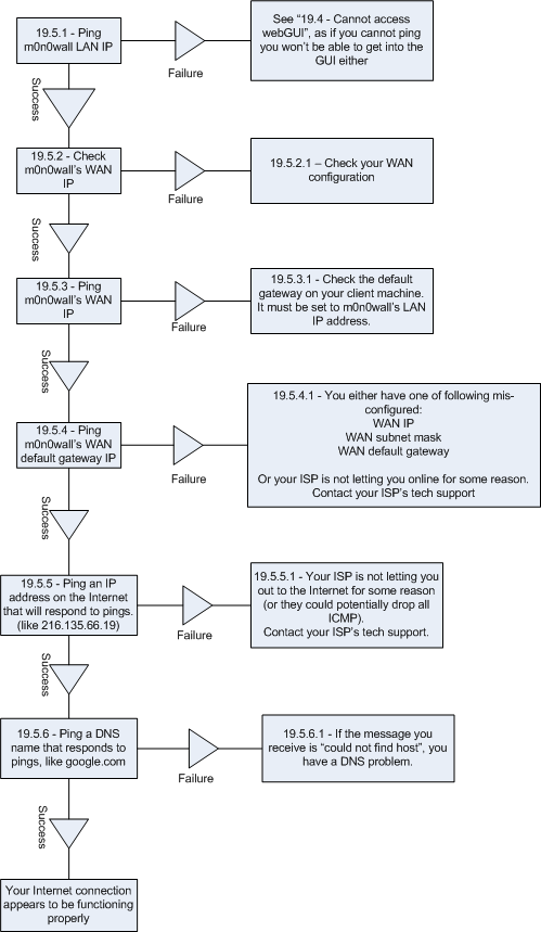
Bring up a command prompt on your machine, type in 'ping 192.168.1.1' and press Enter.
A successful ping will look like the following.
C:\>ping 192.168.1.1

Pinging 192.168.1.1 with 32 bytes of data:

Reply from 192.168.1.1: bytes=32 time<1ms TTL=64
Reply from 192.168.1.1: bytes=32 time<1ms TTL=64
Reply from 192.168.1.1: bytes=32 time<1ms TTL=64
Reply from 192.168.1.1: bytes=32 time<1ms TTL=64

Ping statistics for 192.168.1.1:
    Packets: Sent = 4, Received = 4, Lost = 0 (0% loss),
Approximate round trip times in milli-seconds:
    Minimum = 0ms, Maximum = 0ms, Average = 0ms
An unsuccessful ping will look like this.
C:\>ping 192.168.1.1

Pinging 192.168.1.1 with 32 bytes of data:

Request timed out.
Request timed out.
Request timed out.
Request timed out.

Ping statistics for 192.168.1.1:
    Packets: Sent = 4, Received = 0, Lost = 4 (100% loss),
See Cannot Access webGUI as if you cannot ping, you won't be able to get into the webGUI either.
Go to the Status -> Interfaces page and look under the WAN interface. It must show status as up, and have a valid IP address, subnet mask, and gateway.
If the status shows as "down", check for a link light. See No Link Light if you do not have a link light on your WAN NIC.
If you have a dynamic IP connection like DHCP, PPPoE, or anything but static, and show a 0.0.0.0 IP, you are not getting a lease from your ISP. Check your WAN configuration page to make sure the appropriate settings are entered correctly (like username/password if applicable, etc.).
If you see a WAN IP address on the Status -> Interfaces page, make note of it as you will use it in the next step.
If all settings are correct and you still cannot get a lease and have a DSL or cable modem, try powering off the modem for several seconds and powering it back on. Then go to the WAN interface page, and without saving any changes, click the Save button (or just power cycle m0n0wall if you prefer). Then check the Status -> Interfaces page again to see if you now have an IP address.
If you still don't have an IP and previously had some other router, firewall, or PC connected to this Internet connection, your ISP may be restricting you to only using the MAC address of the previous device. The easiest thing to do in these situations is to get the MAC address off the device that was formerly connected and enter it in the "MAC address" box under "General configuration" on the WAN page in the m0n0wall webGUI. On most routers, you can find the MAC address on a sticker on the device. On Windows PC's, you can get the MAC address by running "ipconfig/all" from a command prompt. On BSD and Linux machines, you can get the MAC address by running 'ifconfig'.
On the Status -> Interfaces page, make note of the WAN IP address. On the client machine you are using, try to ping that IP address.
If the ping is not successful, check the default gateway IP address on the client machine. Run 'ipconfig/all' from a command prompt if using Windows to check this. It must be set to m0n0wall's LAN IP (192.168.1.1 by default).
On the Status -> Interfaces page, make note of m0n0wall's WAN default gateway IP. Try to ping it from your client machine.
If the pings time out, double check your WAN setup. If things fail at this stage, you most likely failed the earlier Check WAN IP step as well.
From the client machine, ping something on the Internet that responds to pings, like 216.135.66.19.
If this fails but all previous steps were successful, your ISP is not letting you out onto the Internet for some reason. At this point, you will need to contact your ISP's technical support. Your ISP could potentially be blocking pings though (not likely), so your pings could time out while your Internet connection still functions (mostly) properly.
First remember rules are processed top down, and the first match is the only rule that applies.
Secondly, remember to check your logs on the Diagnostics -> Logs, Firewall tab. This will show you what is getting dropped due to the default deny all rule. When troubleshooting rules, it can be helpful to enable logging on the rules in question at least temporarily. Remember m0n0wall has limited local logging space, so don't enable too much on a long term basis.
Remember if you need to permit services from the Internet into any private IP space, you need to configure NAT as well as firewall rules, and we recommend using the "auto add firewall rule" when adding NAT entries.
If all else fails and you need to determine exactly which rule is dropping the traffic, go to status.php on your m0n0wall to the "last 50 filter log entries" section. Find the log line applying to the traffic in question, and make note of the rule number. The rule number is denoted by an @ followed by a number, then a colon, then another number, for example @0:18. The 0 indicates the first group, and the 18 indicates rule number 18 in group 0.
Then go up to the output of "ipfstat -nio" and find the rule in question. Anything without a group number at the end of the rule is the 0 group. @1:1 would indicate the first rule with "group 100" at the end of the rule. @2:1 would be the first rule with "group 200" at the end of the rule, and so on. Finding the exact rule, since some rules are added by the back end of m0n0wall and not visible on the rules page, may make troubleshooting easier.
In order to support bridging, the network cards you are using must support promiscuous mode. Not all do. Some people have reported problems with Realtek chipsets not supporting promiscuous mode. To determine if your NIC does, see its documentation.
Check the SAD. Check the Security Association Database (SAD) under Diagnostics. You need to have an entry here for the connection. If you do not, you don't have something configured properly.
Verify Suitable IP Subnets
First make sure the two subnets you are trying to connect don't lie within the same address space. i.e. if both sides are 192.168.1.0/24, the connection will not work. Same goes if one side is 192.168.0.0/16 and the other is 192.168.1.0/24, or similar, the latter lies in the subnet of the former.
If they are within the same address space, you'll need to change one side or the other. There is no way to set up a site to site IPsec VPN with any product when this is the case.
Certain conditions can cause your m0n0wall to freeze solid periodically. The amount of time between freezes typically varies, and can be anywhere from a few hours to a few days.
The first thing to check is whether you have any shared IRQ's. This seems to be the most common cause. If you have recently rebooted your m0n0wall, you should be able to see the boot messages under Diagnostics -> Logs, on the System tab. Otherwise you can go to /exec.php on your m0n0wall and run 'dmesg'. Look through the boot messages and make note of everything you see being shown with an IRQ. This includes your NIC's as well as other devices like serial and parallel ports, etc. An example of some dmesg output follows.
sis0: <NatSemi DP83815 10/100BaseTX> port 0xe000-0xe0ff mem 0xa0001000-0xa0001fff irq 11 at device 18.0 on pci0
sis1: <NatSemi DP83815 10/100BaseTX> port 0xe100-0xe1ff mem 0xa0002000-0xa0002fff irq 5 at device 19.0 on pci0
sis2: <NatSemi DP83815 10/100BaseTX> port 0xe200-0xe2ff mem 0xa0003000-0xa0003fff irq 9 at device 20.0 on pci0
The above example shows three NIC's with IRQ's 11, 5, and 9.
If you note any two devices using a single IRQ, you may need to try other PCI slots, if possible, remove unused cards (like sound cards), and disable unused devices in the BIOS (serial ports, parallel ports, etc.).
You might want to try resetting your BIOS configuration to factory defaults, and then disabling any Plug and Play OS settings. Also check that your BIOS is updated to the latest revision.
Use hardware diagnostic utilities to ensure your RAM and system in general are functioning properly. The Ultimate Boot CD has several utilities for testing CPU and memory.
Hardware overheating is another common cause. This issue has been noted on WRAP hardware especially when using miniPCI cards. It's also possible and has happened with any type of hardware.
If nothing else, it may just be hardware or a combination of hardware that doesn't play nicely with FreeBSD. You may want to try different NIC's or a different system. This especially seems to be a problem with some old AMD K5 and K6 systems, though some work fine.
Table of Contents
This chapter will list all published writings regarding or mentioning m0n0wall in some fashion.
Know of something that isn't listed here? Please email <m0n0wall@chrisbuechler.com>.
Newsforge - For network security, build a m0n0wall
Tom's Networking review, part 2
There will be a session on m0n0wallat O'Reilly's EuroOSCON 2005.
- ACL
Access Control List.
- AH
-
Authentication Header. The Authentication Header is used to provide connectionless integrity and data origin authentication for IP datagrams. Note: AH will not work through NAT, so if you are placing your m0n0wall behind another firewall or layer 2 router that is performing NAT AH will not work. Unless you really have a reason, use ESP.
- Broadcast Domain
-
A broadcast domain is the portion of a network sharing the same layer two network segment. In a network with a single switch, the broadcast domain is that entire switch. In a network with multiple switches interconnected by crossover cables without the use of VLAN's, the broadcast domain includes all of those switches.
A single broadcast domain can contain more than one IP subnet, however that is generally not considered good network design. IP subnets should be segregated into separate broadcast domains via the use of separate switches, or VLAN's.
- DHCP
Dynamic Host Configuration Protocol. A protocol to automate the assignment of IP addresses and related information on a network.
- DMZ
-
A DMZ, or DeMilitarized Zone, is a segment of your network specifically for publicly-accessible servers. If you are most familiar with residential-class routers like Linksys and similar, these devices generally incorrectly refer to inbound NAT (opening ports from the internet to your LAN) as "DMZ" functionality.
A true DMZ resides on a separate broadcast domain from the LAN, typically on a separate switch using a third interface on the firewall. VLAN's can also be used, but to eliminate the potential of a switch misconfiguration exposing your LAN to your DMZ and the potential effects of VLAN hopping attacks, this is not recommended.
The main purpose of a DMZ is to segregate Internet-accessible servers from the LAN, to protect your trusted networks if a DMZ host is compromised.
Typical DMZ Configuration. The following diagram illustrates a typical DMZ configuration.
- ESP
-
Encapsulating Security Payload. Encrypts and / or authenticates everything above the IPsec layer. ESP, most agree, renders AH completely unnecessary.
See Also http://www.networksorcery.com/enp/protocol/esp.htm.
- FQDN
Fully Qualified Domain Name. The host name of a computer, including it's complete domain name, such as www.m0n0.ch.
- ICMP
Internet Control Message Protocol. A protocol, layered on top of IP, used to send control messages between computers, such as ping.
- IP
-
Internet Protocol. The protocol used to send packets across the Internet at layer three.
- IPsec
-
Secure transmission over IP. IPsec is an extension of the IP protocol used for encryption and authentication. Encryption occurs at the transport layer of the OSI model, the application doesn't have to support encryption for the encryption process to work. Therefore, all network traffic generated by applications can be encrypted regardless of the application
See Also http://www.netbsd.org/Documentation/network/ipsec/.
- LAN
-
Local Area Network. A network that typically includes computers which are physically close, such as in one office, usually connected with hubs and switches rather than routers.
- MX Records
MX records are DNS records that enable mail servers to find the mail servers for another domain when sending internet email. When a mail server needs to send an email to example.com, it performs a DNS lookup of the MX record for the domain, and sends the email to the resulting host.
- NIC
Network Interface Card. A.k.a. network card, or Ethernet card.
- NAT
Network Address Translation. A technique whereby IP traffic from multiple IP addresses behind a firewall are made to look to the outside as if they all come from a single IP address.
- OSI
- Proxy ARP
-
Proxy ARP is a technique for using the ARP protocol to provide an ad hoc routing mechanism.
A multi-port networking device (e.g. a router, firewall, etc.) implementing Proxy ARP will respond to ARP requests on one interface as being responsible for addresses of device addresses on another interface. The device can then receive and forward packets addressed to the other devices. (adapted from wikipedia.org)
In m0n0wall, Proxy ARP can be used for 1:1, advanced outbound, and server NAT , amongst other potential uses.
- PPP
Point to Point Protocol.
- PPTP
Point to Point Tunneling Protocol.
- Racoon
-
A key management daemon. The magic behind the VPN power of m0n0wall.
See Also http://www.kame.net/racoon/.
- TCP
Transmission Control Protocol. A protocol, layered on top of IP, that handles connections and reliable delivery.
- VLAN
Virtual Local Area Network. VLAN's are a common function of higher end switches. They allow segregation of ports on the switch into separate broadcast domains. This is generally done for security or performance reasons. In very large networks, the amount of broadcast traffic on the wire can inhibit the performance of the entire network. Segregating the network into multiple IP subnets and using VLAN's to separate the broadcast domain
- VPN
Virtual Private Network. A connection between two or more machines or networks where the data travels over an insecure network (typically the Internet), but is encrypted to prevent eavesdropping, and packaged on either end in order to make the two ends appear to be on a WAN.
- WOL - Wake on LAN
-
Wake on LAN is a capability in some network cards permitting powering on the system over the network with a specially crafted "Magic Packet".
Generally a WOL cable must be attached from the NIC to the motherboard of the system. Most NIC's built into the motherboard have this support built in. You must enable WOL in the BIOS of the machine. This is generally off by default.
- WAN
-
Wide Area Network. A network that spans a large area, typically including routers, gateways, and many different IP address groups.
In the context of firewalls, the WAN interface is the one directly connected to the Internet. In the context of corporate networks, the WAN generally refers to the network that connects all of the organization's locations onto the corporate network. Historically this was accomplished with expensive private leased lines like frame relay and similar technologies. With the low cost and widespread availability of broadband Internet connections, many organizations are switching to using VPN in lieu of leased lines. VPN provides the same functionality, though is not as reliable as leased lines and has higher latency.

Table of Contents
You can change the hostname and domain used by your firewall in the General Setup screen.
NAT (Network Address Translation) permits you to use private IP address space on your LAN while still being able to access the internet.
There are two main types of NAT in m0n0wall, inbound, and 1:1.
You can change the DNS servers used by your firewall in the General Setup screen.
Many operating systems now include free VPN clients for PPTP and IPSec. Although the PPTP VPN of MacOSX and Windows work well with m0n0wall, the IPSec that is included often requires L2TP which m0n0wall does not support.
Because m0n0wall offers an SNMP agent, management and statistics software for network devices can query this agent for information on the status of the firewall itself. This is useful for managing numerous
It is recommended that you log your m0n0wall to a remote syslog server for diagnostics and forensic purposes. There are a number of free tools receive and store syslog messages for you on Windows, Mac, and Unix based systems. These software packages also offer additional features such as automatically sending pages, emails or SMS messages as well as running software or commands based on the messages that are received.
Tip
Log messages include a timestamp of when the event ocurred. The system time on the firewall is synchronized to an NTP (Network Time Protocol) server. You can change the NTP server and related parameters in the General Setup screen.
Unix-based tools
The syslog daemon built into virtually every Unix-like system can be configured to accept log messages from remote hosts. Check documentation specific to your OS on how to configure syslogd to accept messages from remote hosts.
Other Unix Tools
Windows-based tools
There are several free and commercial tools available on Windows to enable your system to accept syslog messages from hosts on your network.
Kiwi Syslog
One of my favorites on Windows is Kiwi Syslog. There is a version with "basic" features that is free, and a more advanced version with $49 registration. Even if you are just looking for a free tool, the basic version has as many if not more features than any other free package on this list. http://www.kiwi-enterprises.com/
3Com offers a couple of free utilities on this page. 3CSyslog is a GUI tool best used on a temporary or as-needed basis only. To collect logs using a service that will be running at all times, whether or not anyone is logged into the machine, try wsyslogd.
Several more for Windows and a couple for Mac listed on this site.
Table of Contents
- B.1. Introduction
- B.2. Installing SVG Viewer on Mozilla Firefox
- B.3. Collecting and Graphing m0n0wall Interface Statistics with ifgraph
- B.4. Updating more than one Dynamic DNS hostname with ddclient
- B.5. Using MultiTech's Free Windows RADIUS Server
- B.6. Configuring Apache for Multiple Servers on One Public IP
- B.7. Opening Ports for BitTorrent in m0n0wall
- B.8. Automated config.xml backup solutions
- B.9. Historical Interface Graphing Using MRTG on Windows
There are a number of third party software packages that provide functionality that m0n0wall does not include. These applications are not installed on m0n0wall, but rather on another system on your LAN. This section of the handbook will document how to use several of these packages.
If you know of other third party applications appropriate for this section of the documentation, please email the editor at m0n0wall@chrisbuechler.com.
The SVG viewer doesn't work "out of the box" after an install like it does in Internet Explorer. See this page on mozilla.org for instructions on installing it.
ifgraph is a nice utility that you can run on a machine on your LAN to query SNMP on your m0n0wall and graph its interfaces. Note that you may be able to hack m0n0wall to run this locally, but if you have a connection with moderate bandwidth and are running on low end hardware like a Soekris 4501, this could limit the device's throughput.
Sample of the web page output of ifgraph on a m0n0wall.
FreeBSD is used in the demonstrated installation as the OS performing the monitoring and hosting the graphs. This will work on other BSD's, Linux or any other Unix OS, but the installation procedures and configuration file locations may vary.
Prerequisites:
Installed and functioning Apache server
m0n0wall SNMP enabled following the instructions in the Users Guide.
1. Install ifgraph.
We'll install ifgraph from FreeBSD ports using binary packages, unless you want to wait for it to compile (doesn't take horribly long). It'll automatically install all the prerequisites either way you do it.
From binary packages
su-2.05b# pkg_add -r ifgraph
Compiling yourself
su-2.05b# cd /usr/ports/net-mgmt/ifgraph
su-2.05b# make install clean
2. Query for interfaces
After the successful ifgraph installation, we will use ifgraph's find-if.pl to find the interface numbers on your m0n0wall. Replace 192.168.1.1 with the LAN IP of your m0n0wall, and 'public' with the SNMP community of your firewall.
su-2.05b# /usr/local/bin/find-if.pl -mi 192.168.1.1 public
OK: session created, getting info from 192.168.1.1
Showing up interfaces of: 192.168.1.1
Interface total: 8
OK: Collecting info on each interface, wait...
Warn: Could NOT get ifPhysAddress table
OK: Data collected
System Description: FreeBSD m0n0wall.local 4.10-RELEASE FreeBSD 4.10-RELEASE #0: Fri Au i386
System Uptime: 3 days, 06:10:58.33
| If #    | Description | Stat | Octets In     | Errors  | Octets Out    | Errors  | IP Address       | MAC Address     |
| ------- | ----------- | ---- | ------------- | ------- | ------------- | ------- | ---------------- | --------------- |
| (1)     | wi0         | up   | 0             | 0       | 11538828      | 0       | not set          | not set         |
| (2)     | sis0        | up   | 3234568017    | 0       | 1783247523    | 0       | 62.22.130.150    | not set         |
| (3)     | sis1        | up   | 0             | 0       | 42            | 0       | 10.1.0.1         | not set         |
| (4)     | sis2        | up   | 1743313091    | 0       | 3020545424    | 0       | 192.168.1.1      | not set         |
| (5)     | lo0         | up   | 732           | 0       | 732           | 0       | 127.0.0.1        | not set         |
You'll see the names of your interfaces under the description column. Make note of the interface number (first column) for your interfaces.
3. Edit ifgraph.conf file.
Copy the sample ifgraph.conf file (ifgraph.conf.sample) to ifgraph.conf.
su-2.05b# cp /usr/local/etc/ifgraph.conf.sample /usr/local/etc/ifgraph.conf
Use the following ifgraph.conf as a template. You will need to replace 192.168.1.1 with the LAN IP address of your m0n0wall, "public" with the SNMP community configured on your m0n0wall, and the "interface=" line to the number of the interface to be graphed.
# [global] target
# This target is mandatory
# The directives of this target are:
# rrdtool = /path/to/rrdtool - full path to rrdtool
# rrddir = /path/to/rrddir - full path to a writeable dir, where
#                     rrd files and logs will be created
# graphdir = /path/to/public_html - full path to a writeable dir,
#                     where png and html will be created
# template = /path/to/template_dir - full path to a directory
#                     containing template files
# imgformat = the image format. You may choose:
#               PNG - Portable Network Graphics
#               GIF - Graphics Interchange Format
#               iGIF - Interlaced GIF
#               GD - Boutell GD
# Defaults: You can define default configurations in the global
# target, but, for this to work, it must be the first target always.
# If [global] is after another target, default configurations
# will not work as expected.

[global]
rrdtool = /usr/local/bin/rrdtool
rrddir = /usr/local/var/ifgraph
graphdir = /usr/local/ifgraph/htdocs
template = /usr/local/ifgraph/templates/en
imgformat=PNG
# those are the default configurations, should be
# overriden in each target

host = your.main.router.com
community = public
port =161
max=100M
dimension=550x200
colors=back#000000,font#FFFFFF,shadea#212121,canvas#232323,mgrid#FF0000,out#FFFFFF
options=noerror
hbeat=600
retry=2
timeout=5

[m0n0wall-wan]
host=192.168.1.1
community=public
port=161
interface=2
max=100M
dimension=550x200
title=In/Out data for m0n0wall WAN interface
colors=back#000000,font#FFFFFF,shadea#212121,canvas#232323,mgrid#FF0000,out#FFFFFF
options=noerror
ylegend=kbits per second
legends=kbits entering our network,kbits leaving our network
shortlegend=kbits/sec
hbeat=600
retry=2
timeout=5
step = 300
periods = -1day, -1week, -1month, -1year

[m0n0wall-dmz]
host=192.168.1.1
community=public
port=161
interface=3
max=100M
dimension=550x200
title=In/Out data for m0n0wall DMZ interface
colors=back#000000,font#FFFFFF,shadea#212121,canvas#232323,mgrid#FF0000,out#FFFFFF
options=noerror
ylegend=kbits per second
legends=kbits entering DMZ network,kbits leaving DMZ network
shortlegend=kbits/sec
hbeat=600
retry=2
timeout=5
step = 300
periods = -1day, -1week, -1month, -1year

[m0n0wall-lan]
host=192.168.1.1
community=public
port=161
interface=4
max=100M
dimension=550x200
title=In/Out data for m0n0wall LAN interface
colors=back#000000,font#FFFFFF,shadea#212121,canvas#232323,mgrid#FF0000,out#FFFFFF
options=noerror
ylegend=kbits per second
legends=kbits entering our LAN network,kbits leaving our LAN network
shortlegend=kbits/sec
hbeat=600
retry=2
timeout=5
step = 300
periods = -1day, -1week, -1month, -1year
4. Run tests.
First we'll run ifgraph.pl to collect the data. Run this at least three times, and wait a few seconds in between runs.
su-2.05b# ifgraph.pl -c /usr/local/etc/ifgraph.conf
Now we'll run makegraph.pl to make the html pages and graphs.
su-2.05b# makegraph.pl -c /usr/local/etc/ifgraph.conf
Check the ifgraph htdocs directory to make sure it contains the png and html files.
su-2.05b# ls /usr/local/ifgraph/htdocs
index.html m0n0wall-lan-1day.png m0n0wall-wan-1month.png
m0n0wall-dmz-1day.png m0n0wall-lan-1month.png m0n0wall-wan-1week.png
m0n0wall-dmz-1month.png m0n0wall-lan-1week.png m0n0wall-wan-1year.png
m0n0wall-dmz-1week.png m0n0wall-lan-1year.png m0n0wall-wan.html
m0n0wall-dmz-1year.png m0n0wall-lan.html
m0n0wall-dmz.html m0n0wall-wan-1day.png
5. Edit Apache config
In the mod_alias section of your httpd.conf file (/usr/local/etc/apache/httpd.conf in FreeBSD)
Alias /ifgraph/ "/usr/local/ifgraph/htdocs/"
Restart Apache for the changes to take effect.
su-2.05b# apachectl restart
6. Open web browser to view graphs.
Open up your web browser and go to http://server/ifgraph/. You should see graphs there, though they probably will not contain any data at this time. If you can't get any web page to appear, you likely have Apache issues. If you see broken images instead of graphs, check step 4 for problems.
7. Add to cron to update automatically.
Open up /etc/crontab in your text editor, and add the following two lines to the bottom of this file.
* * * * * root /usr/local/bin/ifgraph.pl -c /usr/local/etc/ifgraph.conf > /dev/null
*/5 * * * * root /usr/local/bin/makegraph.pl -c /usr/local/etc/ifgraph.conf > /dev/null
This will run the data collection every minute, and make the graphs every 5 minutes. You can change these if you like, but these values generally work out well.
Note that you likely don't have to run this as root. If you want to be cautious, you should create an account with the appropriately limited permissions to run this under.
Make cron re-read its configuration files:
su-2.05b# killall -HUP cron
m0n0wall updates the dynamic hostname of the external interface with the program ez-ipupdate which is lightweight and does its job. However, it is not capable of updating more than one hostname (like if you host your domain at DynDNS). If you want or need to do this, your best bet is using another system (you'll probably have a server running in the background anyway).
The ddclient project website can be found here.
DynDNS has a list of supported clients. Most of these will work with any dynamic DNS provider, not only with DynDNS.
See what DynDNS offers as services. This is vital in understanding the config file of ddclient.
This document describes the setup for updating several hostnames with ddclient. I chose that particular beast because it can read the external address from status pages of several hardware and software firewalls and routers so I thought I might check if it works out of the box with the m0n0wall status_interfaces.php page. It does.
The config is pretty easy:
# Configuration file for ddclient generated by debconf
#
# /etc/ddclient.conf

pid=/var/run/ddclient.pid
protocol=dyndns2
server=members.dyndns.org
login=YourDynDNSLogin
password=YourDynDNSPassword
fw-login=admin
fw-password=Yourm0n0Password
use=fw,  fw=http://Yourm0n0IPOrHostname/status_interfaces.php
custom=yes
yourdomain.org,mail.yourdomain.org,somehost.yourdomain.org,yourdomain.com
If you only want to update Dynamic DNS entries with DynDNS, remove the
custom=yes
directive. If you want to update a DynDNS Static DNS record, replace the
custom=yes
with
static=yes
If you manage your m0n0wall with TLS, the setup is slightly different as you should run an external command to access the status page:
# Configuration file for ddclient generated by debconf
#
# /etc/ddclient.conf

pid=/var/run/ddclient.pid
protocol=dyndns2
server=members.dyndns.org
login=YourDynDNSLogin
password=YourDynDNSPassword
# fw-login=admin
# fw-password=Password
# use=fw,  fw=http://Yourm0n0IPOrHostname/status_interfaces.php
use=cmd
cmd='curl -k -s https://admin:Yourm0n0Password@Yourm0n0IPOrPassword/status_interfaces.php'
custom=yes
yourdomain.org,mail.yourdomain.org,somehost.yourdomain.org,yourdomain.com
Now setup ddclient to run as a daemon. Mine checks the status page every 5 minutes and updates the DynDNS records if necessary.
/usr/sbin/ddclient -daemon 300 -syslog
In this post to the m0n0wall list on September 30, 2004, Barry Mather explains how to set up MultiTech RADIUS server for use with m0n0wall.
Get the software (just google radius200.exe and download from
multi-tech) Install onto you win32 machine, I have it working on both winxp sp2,
and win2k3 server.
If you installed to a default location, open c:\program files\multi-tech
systems\radius server2.00
Open the users file with notepad.
Remove all the users in there, I have the following line for a user:
Username Auth-Type = Local, Password = "userspassword"
The username is the 'username' in the line above is the actual username
you want to use.
The realms file can be empty.
The radius program will create a my-users file based on the users file
you just edited, leave this alone.
Dictionary file can be left as is.
The clients file needs to be edited to include the ip address of the
m0n0wall, and the radius access password, my file looks like this :
172.16.1.1 password
That's it, v simple
No more files to edit.
It installs itself as a win32 service, just stop the service, restart
it, and it loads all the settings / users ..
Now enable the captive portal, telling it to use the ip address of the
win32 machine this radius server is installed on, and the password to
use, in this case password.
Make sure that your local win32 firewall is either not on, or is
allowing port 1812 through for radius!
If you only have one public IP but run multiple web servers, you can set up the others on other port numbers. However giving out URL's like http://www.example.com:81 isn't exactly ideal. You're bound to have people trying to get to http://www.example.com, and since your port 80 points to another web server, the person will get the wrong web page.
You can get around this by using name-based virtual hosting on the web server on port 80. This configuration will work with any web server that supports name-based virtual hosting (most any does), but this section will describe how to configure Apache for this purpose.
For this configuration, port 80 is www.example.com, port 81 is www.whatever.com and port 82 is www.example.net. These are three separate physical web servers.
At the bottom of your httpd.conf (in /usr/local/etc/apache/ in FreeBSD, the location of your configuration file may vary) add the following lines. This is on the server that is accessed via port 80 from the internet.
    NameVirtualHost 192.168.1.12

    <VirtualHost 192.168.1.12>
        UseCanonicalName off
        ServerName www.example.com
        DocumentRoot /usr/local/www/data/
    </VirtualHost>

    <VirtualHost 192.168.1.12>
        UseCanonicalName off
        ServerName www.whatever.com
        Redirect / http://www.whatever.com:81
    </VirtualHost>

    <VirtualHost 192.168.1.12>
        UseCanonicalName off
        ServerName www.example.net
        Redirect / http://www.example.net:82
    </VirtualHost>
That configuration will keep www.example.com local, with the site's files in /usr/local/www/data/, and will redirect any requests to www.whatever.com to www.whatever.com:81 and www.example.net to www.example.net:82.
It's not an ideal setup, but if you're stuck with multiple web servers and a single public IP to reference all of them, it's better than people getting the wrong page when forgetting to put the port after the URL.
For maximum performance when using BitTorrent behind NAT, you should open ports 6881-6889 to your PC. As of version 3.2 and later, BitTorrent uses 6881-6999 though you should be fine with the smaller range.
To open these ports, create an Inbound NAT rule matching the following, changing 192.168.1.22 to the IP address of the system using BitTorrent.
Note
If you aren't already using a static IP or static DHCP reservation, you should set one up for that machine now so its IP address will never change.
The following offers two different ways to automatically back up your m0n0wall configuration. Keep in mind either one requires you saving your firewall password in clear text. This isn't the best idea from a security standpoint, and may not be a risk you are willing to take, depending on your environment. Keep this in mind. At a minimum, make sure you have strong permissions on the .sh file.
Jim Gifford posted the following shell script to the list on January 29, 2004 that automatically backs up the m0n0wall config.xml file and commits it into a CVS repository.
#!/bin/sh
# m0n0back -- backup up a m0n0wall config and puts it into cvs
# depends on: sh, curl, cvs, date, rm

CVSROOT=/cvs
export CVSROOT
CVSPROJ=backup
M0N0IP=192.168.1.1
PROTO=http
USER=admin
PASS=XXXXXX
TMPDIR=/tmp/$$

mkdir $TMPDIR
cd $TMPDIR

cvs -Q co $CVSPROJ
cd $CVSPROJ

curl -s -o config.xml -F Submit=download -u ${USER}:${PASS} ${PROTO}://$M0N0IP/diag_backup.php

NOW=`date +%Y-%m-%d@%H:%M:%S`
cvs -Q commit -m "backup of config.xml [$NOW]"

cd /tmp
rm -rf $TMPDIR
Chris Buechler wrote a shell script to just back up the file with the filename DATE-config.xml, without committing it into CVS.
#!/bin/sh
USER=admin
PASS=XXXXXX
PROTO=http
M0N0IP=192.168.1.1
NOW=`date +%Y-%m-%d@%H:%M`
curl -s -o ${NOW}-config.xml -F Submit=download -u ${USER}:${PASS} ${PROTO}://$M0N0IP/diag_backup.php
If you would like historical graphing of your m0n0wall interfaces, but don't have a Unix box of any sort available, MRTG for Windows is a good solution. There is a howto guide available on the MRTG website.
Before starting that guide, you must enable SNMP on your m0n0wall on the Services -> SNMP screen.
Table of Contents
- C.1. The FreeBSD Copyright
- C.2. The PHP License
- C.3. mini_httpd License
- C.4. ISC DHCP Server License
- C.5. ipfilter License
- C.6. MPD License
- C.7. ez-ipupdate License
- C.8. Circular log support for FreeBSD syslogd License
- C.9. dnsmasq License
- C.10. racoon License
- C.11. General Public License for the software known as MSNTP
- C.12. ucd-snmp License
- C.13. choparp License
- C.14. bpalogin License
- C.15. php-radius License
- C.16. wol License
m0n0wall is Copyright © 2002-2008 by Manuel
Kasper <mk@neon1.net>. All rights reserved.
Redistribution and use in source and binary forms, with or without modification, are permitted provided that the following conditions are met:
Redistributions of source code must retain the above copyright notice, this list of conditions and the following disclaimer.
Redistributions in binary form must reproduce the above copyright notice, this list of conditions and the following disclaimer in the documentation and/or other materials provided with the distribution.
THIS SOFTWARE IS PROVIDED "AS IS'' AND ANY EXPRESS OR IMPLIED WARRANTIES, INCLUDING, BUT NOT LIMITED TO, THE IMPLIED WARRANTIES OF MERCHANTABILITY AND FITNESS FOR A PARTICULAR PURPOSE ARE DISCLAIMED. IN NO EVENT SHALL THE AUTHOR BE LIABLE FOR ANY DIRECT, INDIRECT, INCIDENTAL, SPECIAL, EXEMPLARY, OR CONSEQUENTIAL DAMAGES (INCLUDING, BUT NOT LIMITED TO, PROCUREMENT OF SUBSTITUTE GOODS OR SERVICES; LOSS OF USE, DATA, OR PROFITS; OR BUSINESS INTERRUPTION) HOWEVER CAUSED AND ON ANY THEORY OF LIABILITY, WHETHER IN CONTRACT, STRICT LIABILITY, OR TORT (INCLUDING NEGLIGENCE OR OTHERWISE) ARISING IN ANY WAY OUT OF THE USE OF THIS SOFTWARE, EVEN IF ADVISED OF THE POSSIBILITY OF SUCH DAMAGE.
Copyright 1994-2004 The FreeBSD Project. All rights reserved.
Redistribution and use in source and binary forms, with or without modification, are permitted provided that the following conditions are met:
Redistributions of source code must retain the above copyright notice, this list of conditions and the following disclaimer.
Redistributions in binary form must reproduce the above copyright notice, this list of conditions and the following disclaimer in the documentation and/or other materials provided with the distribution.
THIS SOFTWARE IS PROVIDED BY THE FREEBSD PROJECT ``AS IS'' AND ANY EXPRESS OR IMPLIED WARRANTIES, INCLUDING, BUT NOT LIMITED TO, THE IMPLIED WARRANTIES OF MERCHANTABILITY AND FITNESS FOR A PARTICULAR PURPOSE ARE DISCLAIMED. IN NO EVENT SHALL THE FREEBSD PROJECT OR CONTRIBUTORS BE LIABLE FOR ANY DIRECT, INDIRECT, INCIDENTAL, SPECIAL, EXEMPLARY, OR CONSEQUENTIAL DAMAGES (INCLUDING, BUT NOT LIMITED TO, PROCUREMENT OF SUBSTITUTE GOODS OR SERVICES; LOSS OF USE, DATA, OR PROFITS; OR BUSINESS INTERRUPTION) HOWEVER CAUSED AND ON ANY THEORY OF LIABILITY, WHETHER IN CONTRACT, STRICT LIABILITY, OR TORT (INCLUDING NEGLIGENCE OR OTHERWISE) ARISING IN ANY WAY OUT OF THE USE OF THIS SOFTWARE, EVEN IF ADVISED OF THE POSSIBILITY OF SUCH DAMAGE.
The views and conclusions contained in the software and documentation are those of the authors and should not be interpreted as representing official policies, either expressed or implied, of the FreeBSD Project.
The PHP License, version 3.0 Copyright © 1999 - 2004 The PHP Group. All rights reserved.
Redistribution and use in source and binary forms, with or without modification, is permitted provided that the following conditions are met:
Redistributions of source code must retain the above copyright notice, this list of conditions and the following disclaimer.
Redistributions in binary form must reproduce the above copyright notice, this list of conditions and the following disclaimer in the documentation and/or other materials provided with the distribution.
The name "PHP" must not be used to endorse or promote products derived from this software without prior written permission. For written permission, please contact group@php.net.
Products derived from this software may not be called "PHP", nor may "PHP" appear in their name, without prior written permission from group@php.net. You may indicate that your software works in conjunction with PHP by saying "Foo for PHP" instead of calling it "PHP Foo" or "phpfoo"
-
The PHP Group may publish revised and/or new versions of the license from time to time. Each version will be given a distinguishing version number.
Once covered code has been published under a particular version of the license, you may always continue to use it under the terms of that version. You may also choose to use such covered code under the terms of any subsequent version of the license published by the PHP Group. No one other than the PHP Group has the right to modify the terms applicable to covered code created under this License.
-
Redistributions of any form whatsoever must retain the following acknowledgment:
"This product includes PHP, freely available from <http://www.php.net/>".
THIS SOFTWARE IS PROVIDED BY THE PHP DEVELOPMENT TEAM ``AS IS'' AND ANY EXPRESSED OR IMPLIED WARRANTIES, INCLUDING, BUT NOT LIMITED TO, THE IMPLIED WARRANTIES OF MERCHANTABILITY AND FITNESS FOR A PARTICULAR PURPOSE ARE DISCLAIMED. IN NO EVENT SHALL THE PHP DEVELOPMENT TEAM OR ITS CONTRIBUTORS BE LIABLE FOR ANY DIRECT, INDIRECT, INCIDENTAL, SPECIAL, EXEMPLARY, OR CONSEQUENTIAL DAMAGES (INCLUDING, BUT NOT LIMITED TO, PROCUREMENT OF SUBSTITUTE GOODS OR SERVICES; LOSS OF USE, DATA, OR PROFITS; OR BUSINESS INTERRUPTION) HOWEVER CAUSED AND ON ANY THEORY OF LIABILITY, WHETHER IN CONTRACT, STRICT LIABILITY, OR TORT (INCLUDING NEGLIGENCE OR OTHERWISE) ARISING IN ANY WAY OUT OF THE USE OF THIS SOFTWARE, EVEN IF ADVISED OF THE POSSIBILITY OF SUCH DAMAGE.
Copyright © 1999, 2000 by Jef Poskanzer <jef@acme.com>. All rights reserved.
Redistribution and use in source and binary forms, with or without modification, are permitted provided that the following conditions are met:
Redistributions of source code must retain the above copyright notice, this list of conditions and the following disclaimer.
Redistributions in binary form must reproduce the above copyright notice, this list of conditions and the following disclaimer in the documentation and/or other materials provided with the distribution.
THIS SOFTWARE IS PROVIDED BY THE AUTHOR AND CONTRIBUTORS ``AS IS'' AND ANY EXPRESS OR IMPLIED WARRANTIES, INCLUDING, BUT NOT LIMITED TO, THE IMPLIED WARRANTIES OF MERCHANTABILITY AND FITNESS FOR A PARTICULAR PURPOSE ARE DISCLAIMED. IN NO EVENT SHALL THE AUTHOR OR CONTRIBUTORS BE LIABLE FOR ANY DIRECT, INDIRECT, INCIDENTAL, SPECIAL, EXEMPLARY, OR CONSEQUENTIAL DAMAGES (INCLUDING, BUT NOT LIMITED TO, PROCUREMENT OF SUBSTITUTE GOODS OR SERVICES; LOSS OF USE, DATA, OR PROFITS; OR BUSINESS INTERRUPTION) HOWEVER CAUSED AND ON ANY THEORY OF LIABILITY, WHETHER IN CONTRACT, STRICT LIABILITY, OR TORT (INCLUDING NEGLIGENCE OR OTHERWISE) ARISING IN ANY WAY OUT OF THE USE OF THIS SOFTWARE, EVEN IF ADVISED OF THE POSSIBILITY OF SUCH DAMAGE.
Copyright © 2004 by Internet Systems Consortium, Inc. ("ISC")
Copyright © 1996-2003 by Internet Software Consortium
Permission to use, copy, modify, and distribute this software for any purpose with or without fee is hereby granted, provided that the above copyright notice and this permission notice appear in all copies.
THE SOFTWARE IS PROVIDED "AS IS" AND ISC DISCLAIMS ALL WARRANTIES WITH REGARD TO THIS SOFTWARE INCLUDING ALL IMPLIED WARRANTIES OF MERCHANTABILITY AND FITNESS. IN NO EVENT SHALL ISC BE LIABLE FOR ANY SPECIAL, DIRECT, INDIRECT, OR CONSEQUENTIAL DAMAGES OR ANY DAMAGES WHATSOEVER RESULTING FROM LOSS OF USE, DATA OR PROFITS, WHETHER IN AN ACTION OF CONTRACT, NEGLIGENCE OR OTHER TORTIOUS ACTION, ARISING OUT OF OR IN CONNECTION WITH THE USE OR PERFORMANCE OF THIS SOFTWARE.
Copyright © 1993-2002 by Darren Reed.
The author accepts no responsibility for the use of this software and provides it on an ``as is'' basis without express or implied warranty.
Redistribution and use, with or without modification, in source and binary forms, are permitted provided that this notice is preserved in its entirety and due credit is given to the original author and the contributors.
The license and distribution terms for any publicly available version or derivative of this code cannot be changed. i.e. this code cannot simply be copied, in part or in whole, and put under another distribution license [including the GNU Public License.]
THIS SOFTWARE IS PROVIDED BY THE AUTHOR AND CONTRIBUTORS ``AS IS'' AND ANY EXPRESS OR IMPLIED WARRANTIES, INCLUDING, BUT NOT LIMITED TO, THE IMPLIED WARRANTIES OF MERCHANTABILITY AND FITNESS FOR A PARTICULAR PURPOSE ARE DISCLAIMED. IN NO EVENT SHALL THE AUTHOR OR CONTRIBUTORS BE LIABLE FOR ANY DIRECT, INDIRECT, INCIDENTAL, SPECIAL, EXEMPLARY, OR CONSEQUENTIAL DAMAGES (INCLUDING, BUT NOT LIMITED TO, PROCUREMENT OF SUBSTITUTE GOODS OR SERVICES; LOSS OF USE, DATA, OR PROFITS; OR BUSINESS INTERRUPTION) HOWEVER CAUSED AND ON ANY THEORY OF LIABILITY, WHETHER IN CONTRACT, STRICT LIABILITY, OR TORT (INCLUDING NEGLIGENCE OR OTHERWISE) ARISING IN ANY WAY OUT OF THE USE OF THIS SOFTWARE, EVEN IF ADVISED OF THE POSSIBILITY OF SUCH DAMAGE.
I hate legalese, don't you ?
Copyright © 2003-2004, Archie L. Cobbs, Michael Bretterklieber, Alexander Motin
All rights reserved.
Redistribution and use in source and binary forms, with or without modification, are permitted provided that the following conditions are met:
Redistributions of source code must retain the above copyright notice, this list of conditions and the following disclaimer.
Redistributions in binary form must reproduce the above copyright notice, this list of conditions and the following disclaimer in the documentation and/or other materials provided with the distribution.
Neither the name of the authors nor the names of its contributors may be used to endorse or promote products derived from this software without specific prior written permission.
THIS SOFTWARE IS PROVIDED BY THE COPYRIGHT HOLDERS AND CONTRIBUTORS "AS IS" AND ANY EXPRESS OR IMPLIED WARRANTIES, INCLUDING, BUT NOT LIMITED TO, THE IMPLIED WARRANTIES OF MERCHANTABILITY AND FITNESS FOR A PARTICULAR PURPOSE ARE DISCLAIMED. IN NO EVENT SHALL THE COPYRIGHT OWNER OR CONTRIBUTORS BE LIABLE FOR ANY DIRECT, INDIRECT, INCIDENTAL, SPECIAL, EXEMPLARY, OR CONSEQUENTIAL DAMAGES (INCLUDING, BUT NOT LIMITED TO, PROCUREMENT OF SUBSTITUTE GOODS OR SERVICES; LOSS OF USE, DATA, OR PROFITS; OR BUSINESS INTERRUPTION) HOWEVER CAUSED AND ON ANY THEORY OF LIABILITY, WHETHER IN CONTRACT, STRICT LIABILITY, OR TORT (INCLUDING NEGLIGENCE OR OTHERWISE) ARISING IN ANY WAY OUT OF THE USE OF THIS SOFTWARE, EVEN IF ADVISED OF THE POSSIBILITY OF SUCH DAMAGE.
Copyright © 1998-2001 Angus Mackay. All rights reserved;
This program is free software; you can redistribute it and/or modify it under the terms of the GNU General Public License as published by the Free Software Foundation; either version 2, or (at your option) any later version.
THIS SOFTWARE IS PROVIDED ``AS IS'' AND ANY EXPRESSED OR IMPLIED WARRANTIES, INCLUDING, BUT NOT LIMITED TO, THE IMPLIED WARRANTIES OF MERCHANTABILITY AND FITNESS FOR A PARTICULAR PURPOSE ARE DISCLAIMED. IN NO EVENT SHALL THE AUTHOR BE LIABLE FOR ANY DIRECT, INDIRECT, INCIDENTAL, SPECIAL, EXEMPLARY, OR CONSEQUENTIAL DAMAGES (INCLUDING, BUT NOT LIMITED TO, PROCUREMENT OF SUBSTITUTE GOODS OR SERVICES; LOSS OF USE, DATA, OR PROFITS; OR BUSINESS INTERRUPTION) HOWEVER CAUSED AND ON ANY THEORY OF LIABILITY, WHETHER IN CONTRACT, STRICT LIABILITY, OR TORT (INCLUDING NEGLIGENCE OR OTHERWISE) ARISING IN ANY WAY OUT OF THE USE OF THIS SOFTWARE, EVEN IF ADVISED OF THE POSSIBILITY OF SUCH DAMAGE.
Copyright © 2001 Jeff Wheelhouse (jdw@wwwi.com)
This code was originally developed by Jeff Wheelhouse (jdw@wwwi.com).
Redistribution and use in source and binary forms, with or without modification, are permitted provided that the following conditions are met:
Redistribution of source code must retail the above copyright notice, this list of conditions and the following disclaimer.
Redistributions in binary form must reproduce the above copyright notice, this list of conditions and the following disclaimer in the documentation and/or other materials provided with the distribution.
THIS SOFTWARE IS PROVIDED BY JEFF WHEELHOUSE ``AS IS'' AND ANY EXPRESS OR IMPLIED WARRANTIES, INCLUDING, BUT NOT LIMITED TO, THE IMPLIED WARRANTIES OF MERCHANTABILITY AND FITNESS FOR A PARTICULAR PURPOSE ARE DISCLAIMED. IN NO EVENT SHALL JEFF WHEELHOUSE BE LIABLE FOR ANY DIRECT, INDIRECT, INCIDENTAL, SPECIAL, EXEMPLARY, OR CONSEQUENTIAL DAMAGES (INCLUDING BUT NOT LIMITED TO, PROCUREMENT OF SUBSTITUTE GOODS OR SERVICES; LOSS OF USE, DATA, OR PROFITS; OR BUSINESS INTERRUPTION) HOWEVER CAUSED AND ON ANY THEORY OF LIABILITY, WHETHER IN CONTRACT, STRICT LIABILITY, OR TORT (INCLUDING NEGLIGENCE OR OTHERWISE) ARISING IN ANY WAY OUT OF THE USE OF THIS SOFTWARE, EVEN IF ADVISED OF THE POSSIBILITY OF SUCH DAMAGE.
dnsmasq is Copyright © 2000 Simon Kelley
This program is free software; you can redistribute it and/or modify it under the terms of the GNU General Public License as published by the Free Software Foundation; version 2 dated June, 1991.
This program is distributed in the hope that it will be useful, but WITHOUT ANY WARRANTY; without even the implied warranty of MERCHANTABILITY or FITNESS FOR A PARTICULAR PURPOSE. See the GNU General Public License for more details.
Copyright © 1995, 1996, 1997, 1998, 1999, 2000, 2001, 2002 and 2003 WIDE Project. All rights reserved.
Redistribution and use in source and binary forms, with or without modification, are permitted provided that the following conditions are met:
Redistributions of source code must retain the above copyright notice, this list of conditions and the following disclaimer.
Redistributions in binary form must reproduce the above copyright notice, this list of conditions and the following disclaimer in the documentation and/or other materials provided with the distribution.
Neither the name of the project nor the names of its contributors may be used to endorse or promote products derived from this software without specific prior written permission.
THIS SOFTWARE IS PROVIDED BY THE PROJECT AND CONTRIBUTORS ``AS IS'' AND ANY EXPRESS OR IMPLIED WARRANTIES, INCLUDING, BUT NOT LIMITED TO, THE IMPLIED WARRANTIES OF MERCHANTABILITY AND FITNESS FOR A PARTICULAR PURPOSE ARE DISCLAIMED. IN NO EVENT SHALL THE PROJECT OR CONTRIBUTORS BE LIABLE FOR ANY DIRECT, INDIRECT, INCIDENTAL, SPECIAL, EXEMPLARY, OR CONSEQUENTIAL DAMAGES (INCLUDING, BUT NOT LIMITED TO, PROCUREMENT OF SUBSTITUTE GOODS OR SERVICES; LOSS OF USE, DATA, OR PROFITS; OR BUSINESS INTERRUPTION) HOWEVER CAUSED AND ON ANY THEORY OF LIABILITY, WHETHER IN CONTRACT, STRICT LIABILITY, OR TORT (INCLUDING NEGLIGENCE OR OTHERWISE) ARISING IN ANY WAY OUT OF THE USE OF THIS SOFTWARE, EVEN IF ADVISED OF THE POSSIBILITY OF SUCH DAMAGE.
© Copyright, N.M. Maclaren, 1996, 1997, 2000
© Copyright, University of Cambridge, 1996, 1997, 2000
Free use of MSNTP in source and binary forms is permitted, provided that this entire license is duplicated in all copies, and that any documentation, announcements, and other materials related to use acknowledge that the software was developed by N.M. Maclaren (hereafter refered to as the Author) at the University of Cambridge. Neither the name of the Author nor the University of Cambridge may be used to endorse or promote products derived from this material without specific prior written permission.
The Author and the University of Cambridge retain the copyright and all other legal rights to the software and make it available non-exclusively. All users must ensure that the software in all its derivations carries a copyright notice in the form:
© Copyright N.M. Maclaren,
© Copyright University of Cambridge.
NO WARRANTY
Because the MSNTP software is licensed free of charge, the Author and the University of Cambridge provide absolutely no warranty, either expressed or implied, including, but not limited to, the implied warranties of merchantability and fitness for a particular purpose. The entire risk as to the quality and performance of the MSNTP software is with you. Should MSNTP prove defective, you assume the cost of all necessary servicing or repair.
In no event, unless required by law, will the Author or the University of Cambridge, or any other party who may modify and redistribute this software as permitted in accordance with the provisions below, be liable for damages for any losses whatsoever, including but not limited to lost profits, lost monies, lost or corrupted data, or other special, incidental or consequential losses that may arise out of the use or inability to use the MSNTP software.
COPYING POLICY
Permission is hereby granted for copying and distribution of copies of the MSNTP source and binary files, and of any part thereof, subject to the following license conditions:
You may distribute MSNTP or components of MSNTP, with or without additions developed by you or by others. No charge, other than an "at-cost" distribution fee, may be charged for copies, derivations, or distributions of this material without the express written consent of the copyright holders.
You may also distribute MSNTP along with any other product for sale, provided that the cost of the bundled package is the same regardless of whether MSNTP is included or not, and provided that those interested only in MSNTP must be notified that it is a product freely available from the University of Cambridge.
If you distribute MSNTP software or parts of MSNTP, with or without additions developed by you or others, then you must either make available the source to all portions of the MSNTP system (exclusive of any additions made by you or by others) upon request, or instead you may notify anyone requesting source that it is freely available from the University of Cambridge.
You may not omit any of the copyright notices on either the source files, the executable files, or the documentation.
You may not omit transmission of this License agreement with whatever portions of MSNTP that are distributed.
Any users of this software must be notified that it is without warranty or guarantee of any nature, express or implied, nor is there any fitness for use represented.
October 1996
April 1997
October 2000
Copyright 1989, 1991, 1992 by Carnegie Mellon University
Derivative Work - 1996, 1998-2000
Copyright 1996, 1998-2000 The Regents of the University of California
All Rights Reserved
Permission to use, copy, modify and distribute this software and its documentation for any purpose and without fee is hereby granted, provided that the above copyright notice appears in all copies and that both that copyright notice and this permission notice appear in supporting documentation, and that the name of CMU and The Regents of the University of California not be used in advertising or publicity pertaining to distribution of the software without specific written permission.
CMU AND THE REGENTS OF THE UNIVERSITY OF CALIFORNIA DISCLAIM ALL WARRANTIES WITH REGARD TO THIS SOFTWARE, INCLUDING ALL IMPLIED WARRANTIES OF MERCHANTABILITY AND FITNESS. IN NO EVENT SHALL CMU OR THE REGENTS OF THE UNIVERSITY OF CALIFORNIA BE LIABLE FOR ANY SPECIAL, INDIRECT OR CONSEQUENTIAL DAMAGES OR ANY DAMAGES WHATSOEVER RESULTING FROM THE LOSS OF USE, DATA OR PROFITS, WHETHER IN AN ACTION OF CONTRACT, NEGLIGENCE OR OTHER TORTIOUS ACTION, ARISING OUT OF OR IN CONNECTION WITH THE USE OR PERFORMANCE OF THIS SOFTWARE.
Copyright © 2001-2002, Networks Associates Technology, Inc
All rights reserved.
Redistribution and use in source and binary forms, with or without modification, are permitted provided that the following conditions are met:
Redistributions of source code must retain the above copyright notice, this list of conditions and the following disclaimer.
Redistributions in binary form must reproduce the above copyright notice, this list of conditions and the following disclaimer in the documentation and/or other materials provided with the distribution.
Neither the name of the Networks Associates Technology, Inc nor the names of its contributors may be used to endorse or promote products derived from this software without specific prior written permission.
THIS SOFTWARE IS PROVIDED BY THE COPYRIGHT HOLDERS AND CONTRIBUTORS ``AS IS'' AND ANY EXPRESS OR IMPLIED WARRANTIES, INCLUDING, BUT NOT LIMITED TO, THE IMPLIED WARRANTIES OF MERCHANTABILITY AND FITNESS FOR A PARTICULAR PURPOSE ARE DISCLAIMED. IN NO EVENT SHALL THE COPYRIGHT HOLDERS OR CONTRIBUTORS BE LIABLE FOR ANY DIRECT, INDIRECT, INCIDENTAL, SPECIAL, EXEMPLARY, OR CONSEQUENTIAL DAMAGES (INCLUDING, BUT NOT LIMITED TO, PROCUREMENT OF SUBSTITUTE GOODS OR SERVICES; LOSS OF USE, DATA, OR PROFITS; OR BUSINESS INTERRUPTION) HOWEVER CAUSED AND ON ANY THEORY OF LIABILITY, WHETHER IN CONTRACT, STRICT LIABILITY, OR TORT (INCLUDING NEGLIGENCE OR OTHERWISE) ARISING IN ANY WAY OUT OF THE USE OF THIS SOFTWARE, EVEN IF ADVISED OF THE POSSIBILITY OF SUCH DAMAGE.
Portions of this code are copyright © 2001-2002, Cambridge Broadband Ltd.
All rights reserved.
Redistribution and use in source and binary forms, with or without modification, are permitted provided that the following conditions are met:
Redistributions of source code must retain the above copyright notice, this list of conditions and the following disclaimer.
Redistributions in binary form must reproduce the above copyright notice, this list of conditions and the following disclaimer in the documentation and/or other materials provided with the distribution.
The name of Cambridge Broadband Ltd. may not be used to endorse or promote products derived from this software without specific prior written permission.
THIS SOFTWARE IS PROVIDED BY THE COPYRIGHT HOLDER ``AS IS'' AND ANY EXPRESS OR IMPLIED WARRANTIES, INCLUDING, BUT NOT LIMITED TO, THE IMPLIED WARRANTIES OF MERCHANTABILITY AND FITNESS FOR A PARTICULAR PURPOSE ARE DISCLAIMED. IN NO EVENT SHALL THE COPYRIGHT HOLDER BE LIABLE FOR ANY DIRECT, INDIRECT, INCIDENTAL, SPECIAL, EXEMPLARY, OR CONSEQUENTIAL DAMAGES (INCLUDING, BUT NOT LIMITED TO, PROCUREMENT OF SUBSTITUTE GOODS OR SERVICES; LOSS OF USE, DATA, OR PROFITS; OR BUSINESS INTERRUPTION) HOWEVER CAUSED AND ON ANY THEORY OF LIABILITY, WHETHER IN CONTRACT, STRICT LIABILITY, OR TORT (INCLUDING NEGLIGENCE OR OTHERWISE) ARISING IN ANY WAY OUT OF THE USE OF THIS SOFTWARE, EVEN IF ADVISED OF THE POSSIBILITY OF SUCH DAMAGE.
choparp - cheap & omitted proxy arp
Copyright © 1997 Takamichi Tateoka (tree@mma.club.uec.ac.jp)
Copyright © 2002 Thomas Quinot (thomas@cuivre.fr.eu.org)
Redistribution and use in source and binary forms, with or without modification, are permitted provided that the following conditions are met:
Redistributions of source code must retain the above copyright notice, this list of conditions and the following disclaimer.
Redistributions in binary form must reproduce the above copyright notice, this list of conditions and the following disclaimer in the documentation and/or other materials provided with the distribution.
Neither the name of the authors nor the names of their contributors may be used to endorse or promote products derived from this software without specific prior written permission.
THIS SOFTWARE IS PROVIDED BY THE AUTHORS AND CONTRIBUTORS ``AS IS'' AND ANY EXPRESS OR IMPLIED WARRANTIES, INCLUDING, BUT NOT LIMITED TO, THE IMPLIED WARRANTIES OF MERCHANTABILITY AND FITNESS FOR A PARTICULAR PURPOSE ARE DISCLAIMED. IN NO EVENT SHALL THE REGENTS OR CONTRIBUTORS BE LIABLE FOR ANY DIRECT, INDIRECT, INCIDENTAL, SPECIAL, EXEMPLARY, OR CONSEQUENTIAL DAMAGES (INCLUDING, BUT NOT LIMITED TO, PROCUREMENT OF SUBSTITUTE GOODS OR SERVICES; LOSS OF USE, DATA, OR PROFITS; OR BUSINESS INTERRUPTION) HOWEVER CAUSED AND ON ANY THEORY OF LIABILITY, WHETHER IN CONTRACT, STRICT LIABILITY, OR TORT (INCLUDING NEGLIGENCE OR OTHERWISE) ARISING IN ANY WAY OUT OF THE USE OF THIS SOFTWARE, EVEN IF ADVISED OF THE POSSIBILITY OF SUCH DAMAGE.
BPALogin - lightweight portable BIDS2 login client
Copyright © 2001-3 Shane Hyde, and others.
This program is free software; you can redistribute it and/or modify it under the terms of the GNU General Public License as published by the Free Software Foundation; either version 2 of the License, or (at your option) any later version.
This program is distributed in the hope that it will be useful, but WITHOUT ANY WARRANTY; without even the implied warranty of MERCHANTABILITY or FITNESS FOR A PARTICULAR PURPOSE. See the GNU General Public License for more details.
Copyright 2000, 2001, 2002 by Edwin Groothuis. All rights reserved.
Redistribution and use in source and binary forms, with or without modification, are permitted provided that the following conditions are met:
Redistributions of source code must retain the above copyright notice, this list of conditions and the following disclaimer.
Redistributions in binary form must reproduce the above copyright notice, this list of conditions and the following disclaimer in the documentation and/or other materials provided with the distribution.
-
All advertising materials mentioning features or use of this software must display the following acknowledgement:
This product includes software developed by Edwin Groothuis.
Neither the name of Edwin Groothuis may be used to endorse or promote products derived from this software without specific prior written permission.
THIS SOFTWARE IS PROVIDED ``AS IS'' AND ANY EXPRESS OR IMPLIED WARRANTIES, INCLUDING, BUT NOT LIMITED TO, THE IMPLIED WARRANTIES OF MERCHANTABILITY AND FITNESS FOR A PARTICULAR PURPOSE ARE DISCLAIMED. IN NO EVENT SHALL THE REGENTS OR CONTRIBUTORS BE LIABLE FOR ANY DIRECT, INDIRECT, INCIDENTAL, SPECIAL, EXEMPLARY, OR CONSEQUENTIAL DAMAGES (INCLUDING, BUT NOT LIMITED TO, PROCUREMENT OF SUBSTITUTE GOODS OR SERVICES; LOSS OF USE, DATA, OR PROFITS; OR BUSINESS INTERRUPTION) HOWEVER CAUSED AND ON ANY THEORY OF LIABILITY, WHETHER IN CONTRACT, STRICT LIABILITY, OR TORT (INCLUDING NEGLIGENCE OR OTHERWISE) ARISING IN ANY WAY OUT OF THE USE OF THIS SOFTWARE, EVEN IF ADVISED OF THE POSSIBILITY OF SUCH DAMAGE.
wol - wake on lan client
Copyright © 2000,2001,2002,2003,2004 Thomas Krennwallner <krennwallner@aon.at>
This program is free software; you can redistribute it and/or modify it under the terms of the GNU General Public License as published by the Free Software Foundation; either version 2 of the License, or (at your option) any later version.
This program is distributed in the hope that it will be useful, but WITHOUT ANY WARRANTY; without even the implied warranty of MERCHANTABILITY or FITNESS FOR A PARTICULAR PURPOSE. See the GNU General Public License for more details.
You should have received a copy of the GNU General Public License along with this program; if not, write to the Free Software Foundation, Inc., 59 Temple Place - Suite 330, Boston, MA 02111-1307, USA.